LED (light emitting diode) constant current driving circuit with current detection and LED backlight system

A constant current drive and current detection technology, applied in the electronic field, can solve the problems of no inductor and power tube, the inability to guarantee the constant current of the LED light string, and the inability to achieve system applications, etc.

Inactive Publication Date: 2011-09-14
深圳市科铭实业有限公司
View PDF4 Cites 39 Cited by
  • Summary
  • Abstract
  • Description
  • Claims
  • Application Information

AI Technical Summary

Problems solved by technology

The biggest disadvantage of this kind of circuit when driving LED light strings is that the driver chip can only ensure a constant voltage on the LED light string, but cannot guarantee a constant current on the LED light string.
At the same time, since the system only feeds back the voltage on the LED light string, it is impossible to judge whether there is an open circuit or a short circuit in the LED light string, so it cannot meet the requirements of the system application.
[0003] The Chinese invention patent application number is: "02824219.X", the name is: "LED drive circuit with PWM" output discloses a drive circuit that uses pulse width modulation (PWM) to provide power for LEDs, and the drive circuit uses current feedback To adjust the power of the LED array, but the circuit only relies on current feedback to adjust the control current, and it is impossible to judge whether the LED light string is open or short circuited.
In addition, the above-mentioned patent simply uses the feedback current for adjustment, and there are no inductors and power tubes outside it, so it is impossible to calculate the minimum current and judge whether there is a problem with the light string.

Method used


Image

  • LED (light emitting diode) constant current driving circuit with current detection and LED backlight system
  • LED (light emitting diode) constant current driving circuit with current detection and LED backlight system
  • LED (light emitting diode) constant current driving circuit with current detection and LED backlight system

Examples


Embodiment Construction

[0021] In order to describe the technical content, structural features, achieved goals and effects of the present invention in detail, the following will be described in detail in conjunction with the embodiments and accompanying drawings.

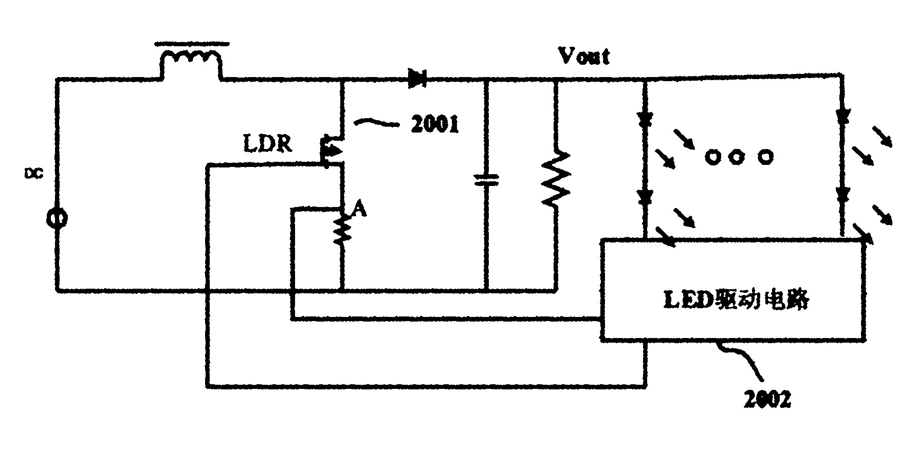
[0022] see figure 2 In the application circuit diagram of the driving circuit of the present invention, the driving circuit 2002 adjusts the duty ratio of the control signal of the switching tube by feeding back the minimum current in the LED string and combining the two loops of the inductor current value. To achieve a constant LED string current. Simultaneously detect the LED string current and output terminal voltage to judge whether there is an open circuit or short circuit in the LED light string. When there is a problem with all LED light strings, no current is output.

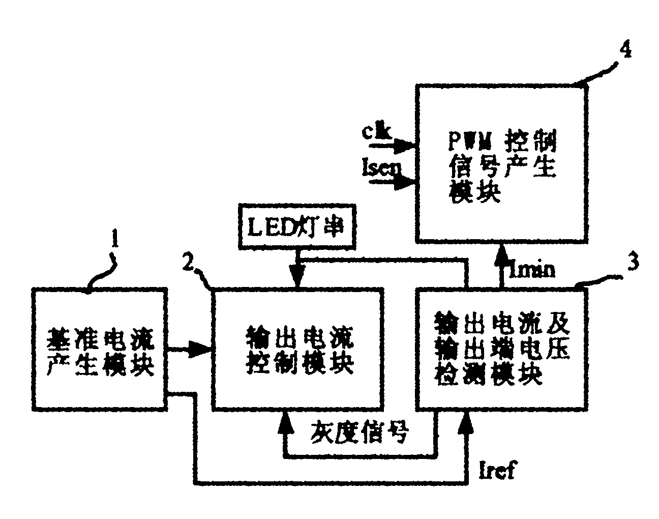
[0023] see image 3, the LED constant current drive circuit with current detection of the present invention includes a reference voltage module (not shown), a re...


PUM


Abstract

The invention discloses an LED (light emitting diode) constant current driving circuit with current detection and an LED backlight system. The LED constant current driving circuit with current detection comprises a reference voltage module, a reference current generating module, an output current control module, an output current and output end voltage detection module and a PWM (pulse width modulation) control signal generating module. According to the invention, the control signal duty cycle of a switching tube is adjusted by feeding back the minimum current in LED light string so as to drive LED light string by constant current. Meanwhile, the current and output voltage of the LED light string is detected to judge whether the LED light string undergoes open circuit or short circuit; and when all LED light strings have problem, the output current control module is controlled to close the current output.

Description

technical field [0001] The invention relates to the field of electronics, in particular to an LED constant current drive circuit with current detection and an LED backlight system. Background technique [0002] The traditional step-up switching power supply LED drive circuit such as figure 1 Shown in 1001. The driving chip adjusts the PWM duty cycle of the switching tube through two loops of feeding back the current on the inductor 1003 and feeding back the output voltage Vout, so as to achieve the purpose of stabilizing the voltage. The biggest disadvantage of this kind of circuit when driving the LED light string is that the driver chip can only ensure the constant voltage on the LED light string, but cannot guarantee the constant current on the LED light string. At the same time, since the system only feeds back the voltage on the LED light string, it is impossible to judge whether the LED light string has an open circuit or a short circuit, thus failing to meet the req...

Claims


Application Information

Patent Timeline
Patent Type & Authority Applications(China)
IPC IPC(8): H05B37/02G01R31/02
CPCY02B20/42Y02B20/40
Inventor 林昕林丰成林乔嵩王莉孙丽娟
Owner 深圳市科铭实业有限公司
Why Eureka
Try Eureka