Single live wire power-getting circuit

A technology of single fire wire and switching power supply circuit, which is applied in the direction of lamp circuit layout, electric light source, lighting device, etc., and can solve the problems of insufficient power supply of the back-end wireless module, inability to use zigbee chip single fire wire work, and inability to connect large loads, etc.

Inactive Publication Date: 2011-09-14
NANJING IOT SENSOR TECH
View PDF3 Cites 27 Cited by
  • Summary
  • Abstract
  • Description
  • Claims
  • Application Information

AI Technical Summary

Problems solved by technology

[0002] In the smart home control system, the current single FireWire products on the market have the following deficiencies through test results: insufficient power supply to the back-end wireless module, problems such as inability to connect large loads, etc. For example, the zigbee wireless chip needs current when sending and receiving data More than 30mA, the wireless single live wire products on the market are suitable for 433 / 315 and other wireless technologies that only need a small current (hundreds of microamps to several milliamperes) to work, and cannot be applied to the single live wire work of the zigbee chip

Method used


Image

  • Single live wire power-getting circuit
  • Single live wire power-getting circuit
  • Single live wire power-getting circuit

Examples


Embodiment Construction

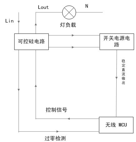
[0018] like figure 1 , the single live wire power-taking circuit of the present invention mainly includes a silicon controlled rectifier circuit, a switching power supply circuit and an MCU circuit, wherein:

[0019] The current input terminal of the thyristor circuit is connected to the 220V live wire (Lin means 220V live wire input), the current output (Lout means the live wire output) end is connected to the lamp load, and the other end of the lamp load is connected to the neutral wire, and the thyristor control circuit is also connected to the switching power supply circuit , and then the switching power supply circuit provides DC output to the MCU circuit, and the MCU circuit outputs the control signal to the control signal receiving end of the thyristor circuit

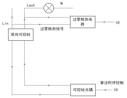
[0020] The thyristor circuit includes bidirectional thyristor, thyristor optocoupler, and zero-crossing detection circuit. The zero-crossing detection signal is sent to an IO port of MCU for real-time detection ...


PUM


Abstract

The invention discloses a single live wire power-getting circuit. The single live wire power-getting circuit comprises a silicon controlled rectifier circuit, a switching mode power supply circuit and a micro control unit (MCU) circuit, wherein the silicon controlled rectifier circuit gets power from a live wire; an input end loop of the switching mode power supply circuit is connected with the output end of the silicon controlled rectifier circuit; the switching mode power supply circuit outputs stable direct voltage with high loading capability to the MCU circuit; the input end of the MCU circuit is connected with the signal output end of the silicon controlled rectifier circuit; and the output end of the MCU circuit outputs a sequential control signal to the signal receiving end of the silicon controlled rectifier circuit to adjust a conduction angle of the silicon controlled rectifier. In the invention, the zero crossing point of alternating current is detected in real time through the MCU circuit, so that a control signal is transmitted, control over the conduction angle of the silicon controlled rectifier is realized, and the aim of regulating load light is fulfilled. For the MCU circuit, the conduction angle of the silicon controlled rectifier can be controlled through a keypad and wireless data to fulfill the aim of regulating the light. The single live wire power-getting circuit can ensure the stable operation of the rear-end switching mode power supply and provide stable voltage for rear-end equipment for operation at the same time of light regulation.

Description

technical field [0001] The invention relates to a wireless single live wire dimming circuit, in particular to a single live wire power-taking circuit, which can supply the back-end wireless module to work after the power is taken. technical background [0002] In the smart home control system, the current single FireWire products on the market have the following deficiencies through test results: insufficient power supply to the back-end wireless module, problems such as inability to connect large loads, etc. For example, the zigbee wireless chip needs current when sending and receiving data More than 30mA, the wireless single live wire products on the market are suitable for wireless technologies such as 433 / 315 that only require a small current (hundreds of microamps to several milliamperes) to work, and cannot be applied to the single live wire work of the zigbee chip. Contents of the invention [0003] The technical problem to be solved by the present invention is to p...

Claims


Application Information

Patent Timeline
IPC IPC(8): H05B37/02
CPCY02B20/42Y02B20/40
Inventor 朱峰朱俊岭朱俊岗余建美
Owner NANJING IOT SENSOR TECH
Why Eureka
Try Eureka