
Polygonal driving means with inbuilt collar

A driving component, polygonal technology, applied in the direction of connecting components, threaded fasteners, screws, etc., can solve the problem that it is impossible to forge angular shapes, etc., to achieve easy identification and improve the effect of heat dissipation

Active Publication Date: 2011-09-14
LISI AEROSPACE
View PDF4 Cites 3 Cited by
  • Summary
  • Abstract
  • Description
  • Claims
  • Application Information

AI Technical Summary

Problems solved by technology

In practice it is not possible to forge the same angular shape as this presents a material filling problem

Method used


Image

  • Polygonal driving means with inbuilt collar
  • Polygonal driving means with inbuilt collar
  • Polygonal driving means with inbuilt collar

Examples


Embodiment Construction

[0062] Figure 3A An oblique perspective view of a first example of a nut with a drive part 23 with a frusto-conical flange 6 according to the invention is schematically shown. In an example, the drive part 23 shown on the lower view and its variants are obtained by forging using a die. In a variant, the drive part can also be obtained by another manufacturing method, such as machining, moulding, injection molding, calcination, so that whatever the manufacturing method is used, it has the same driving part in use. The drive part 23 comprises a polygonal, here hexagonal, shank 7 and a frustoconical flange 6 . According to the invention, the flange 6 is provided with a depressed side surface 24 . In the example of FIG. 3 , the side surface 24 is flat. According to the invention, depression means that a surface portion is inclined inwardly with respect to the frusto-conical curved surface. The circular base 18 of the cone of the flange 6 extends to a cylinder 19 . The drive ...


PUM


Abstract

It has become apparent that the dimensions of inbuilt-collar driving means of the same nominal size can vary according to the manufacturing process. The dimensions of the collar have to be adapted to suit the method of manufacture accordingly, at the expense of strength or mass. In addition, the torque that can be transmitted for tightening and loosening varies according to a useful height on which a wrench can gain a purchase. The idea underlying the invention, in order to have a useful height identical to the height of shank (7) is for the frustoconical collar (152) of a driving means (151) to be pushed in towards its centre in the continuation of the faces of the shank. The driving means with inbuilt collar proposed by the invention is suited to all methods of manufacture, and can be manufactured without adversely affecting the dimensions of the driving means or how it is fitted.

Description

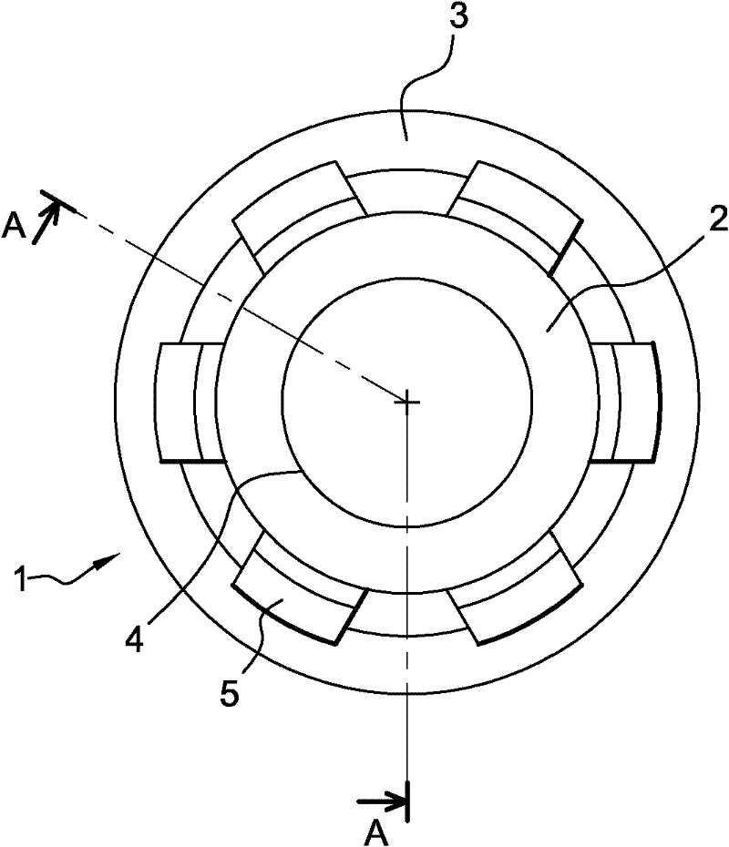
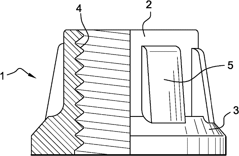
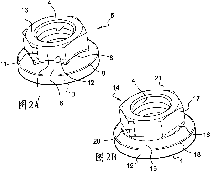
technical field [0001] The invention relates to a polygonal drive element with a recessed flange with recessed sides. [0002] The technical field of the invention is generally that of drive components. More particularly, the invention relates to nuts and screws with recessed flanges of the frusto-conical type. Background technique [0003] In the prior art, the teaching of the utility model USD206402 is especially known, which is disclosed in Figure 1A and 1B Reinforced nut with frusto-conical flange shown schematically above. [0004] Figure 1A Shows a front view of this type of nut 1 while Figure 1B A partially cut-away side view of the same nut 1 is shown. The cutting plane is determined by plane A-A. The nut 1 comprises a shank 2 and a frusto-conical flange 3 . The cylindrical inner wall 4 of the nut 1 is threaded and may have a bore. Six pillars 5 connect the flange 3 with the handle body 2 . [0005] In the prior art, it is also known as in Figure 2A and ...

Claims


Application Information

Patent Timeline
Patent Type & Authority Applications(China)
IPC IPC(8): F16B23/00F16B37/00
CPCF16B37/00F16B23/0061F16B33/06
Inventor A·贝尔东N·格兰
Owner LISI AEROSPACE
Learn More