Oil removal releaser

A releaser, positive surface technology, applied in chemical instruments and methods, grease/oily substance/float removal devices, flotation water/sewage treatment, etc. Pollution, water environment pollution and other problems, achieve good economic and social benefits, reduce labor intensity, and overcome the effects of equipment downtime

Active Publication Date: 2011-09-21
JIANGSU XINGCHEN ENVIRONMENTAL PROTECTION GROUP
View PDF5 Cites 0 Cited by
  • Summary
  • Abstract
  • Description
  • Claims
  • Application Information

AI Technical Summary

Problems solved by technology

If the oily wastewater is discharged directly without treatment, it will cause serious pollution to the water environment on the one hand, and on the other hand, because a large area of ​​our country is in a state of water shortage, the price of water is constantly rising, and a large amount of oily wastewater Direct discharge of wastewater is an extreme waste of water resources, so how to treat and reuse oily wastewater has very important practical significance for controlling water pollution and saving water resources
Due to the wide range of sources of oily wastewater, most of the related technical reports seen so far are processes for treating wastewater with a large oil content, and oil-water separators are often used for oil-water separation and then directly discharged. It is difficult to achieve wastewater discharge and recycling. used standard
Therefore, the deficiency in the current prior art is that the oily wastewater cannot be effectively treated, resulting in pollution and waste of water resources.

Method used


Image

  • Oil removal releaser
  • Oil removal releaser
  • Oil removal releaser

Examples


Embodiment Construction

[0013] The present invention will be further explained below in conjunction with the accompanying drawings.

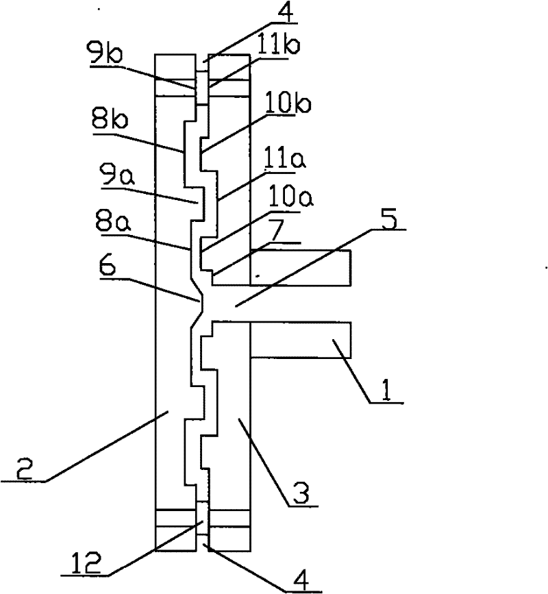
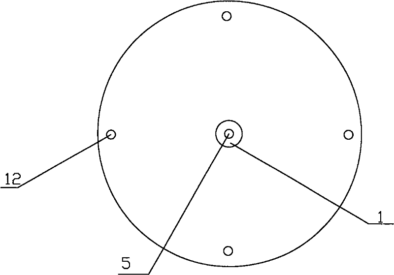
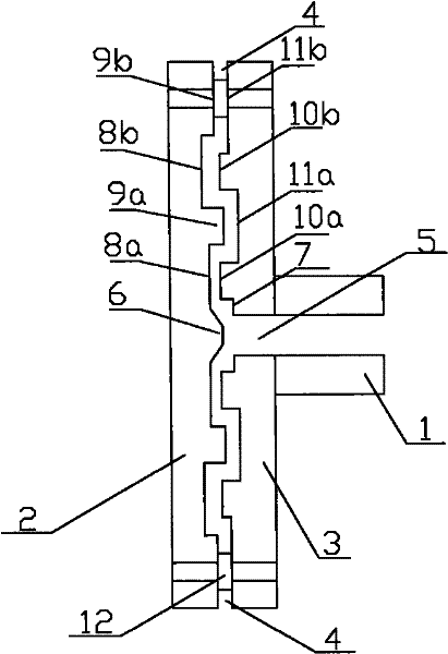
[0014] The invention discloses a degreasing releaser. The degreasing releaser is in the shape of a perfectly circular disc, including a positive surface 3 and a negative surface 2. The center of one side of the negative surface 2 is a conical protrusion 6, which is outward from the conical protrusion 6. There are two annular grooves 8 and two annular bosses 9 concentric with the conical protrusion 6, the grooves 8 and the bosses 9 are arranged alternately, the innermost circle is a groove 8a, and the negative surface 2 The other side is horizontal; the center of the positive surface 3 is a circular groove 7, and from the circular groove 7 there are two annular bosses 10 and two annular bosses 10 concentric with the circular groove 7. Grooves 11, the grooves 11 and the bosses 10 are arranged alternately, the innermost circle is the bosses 10a, the center of the circular...


PUM

PropertyMeasurementUnit
diameteraaaaaaaaaa

Abstract

The invention discloses an oil removal releaser, which has a discoid shape and comprises a shady side and a sunny side. A conical protuberance is at a center of one side of the shady side, annular grooves and annular bosses are arranged from a near position to a far position of the conical protuberance in an alternative manner, and the other side of the shady side is flat. A circular groove is ata center of the sunny side, annular bosses and annular grooves are arranged from a near position to a far position of the circular groove in the alternative manner, a through hole is arranged at a center of the circular groove, and a solution import is arranged on the through hole position of the other side of the sunny side. The shady side has a welding connection with the sunny side by a plastic column, and a water outlet is arranged at a most outside position of a gap between the shady side and the sunny side. According to the invention, the oil removal releaser allows pressure reduction to be uniform, obstruction to be avoided automatically, operation to be convenient and labor intensity to be reduced, fine bubbles released by the releaser have an average diameter of less than 20 <mu>m, and the oil removal efficiency is improved more than one time. So the releaser can be widely applied to multiple fields, and allows good economic benefits and social benefits to be generated.

Description

technical field [0001] The invention relates to a release device suitable for liquid release in metallurgy and chemical industries, in particular to an oil removal releaser. Background technique [0002] Whether in the industrial field or in daily life, a considerable proportion of the discharged sewage is oily wastewater. If the oily wastewater is discharged without treatment, it will cause serious pollution to the water environment. On the other hand, since a large area of ​​our country is in a state of water shortage, the price of water is constantly rising, and a large amount of oily wastewater Direct discharge of wastewater is an extreme waste of water resources, so how to treat and reuse oily wastewater has very important practical significance for controlling water pollution and saving water resources. Due to the wide range of sources of oily wastewater, most of the relevant technical reports seen so far are processes for treating wastewater with a large oil content,...

Claims


Application Information

Patent Timeline
Patent Type & Authority Applications(China)
IPC IPC(8): C02F1/24C02F1/40C02F101/32
Inventor 丁叶民
Owner JIANGSU XINGCHEN ENVIRONMENTAL PROTECTION GROUP
Why Eureka
Try Eureka