Axial plunger pump with double rows of cylinder holes and cylinder bodies

A technology of axial plunger pump and cylinder hole, which is applied to multi-cylinder pumps, parts of pumping devices for elastic fluids, pumps, etc., and can solve the problem of aggravated wear of sliding shoes and wobble plates, plungers and cylinder holes, Increase the diameter of the cylinder bore, increase the size of the cylinder pump body, etc., to achieve the effects of prolonging the life, increasing the frequency of oil discharge, and increasing the flow rate

Inactive Publication Date: 2011-09-21
BEIJING HUADE HYDRAULIC INDAL GROUP
View PDF6 Cites 8 Cited by
  • Summary
  • Abstract
  • Description
  • Claims
  • Application Information

AI Technical Summary

Problems solved by technology

[0004] 1. Increase the diameter of the cylinder bore. The increase in the diameter of the cylinder bore will inevitably lead to the enlargement of the cylinder block and even the entire pump body.
[0005] 2. Increase the stroke of the plunger. The stroke of the plunger depends on the inclination angle of the wobble plate. However, the increase of the inclination angle of the wobble plate will lead to an increase in the radial component force between the action of the wobble plate and the contact end of the plunger, and a decrease in the axial component force. The result is : The output pressure is reduced, and the wear of the sliding shoe and the swing plate, as well as the plunger and the cylinder hole is aggravated
[0006] 3. Increase the number of cylinder holes, the increase in the number of cylinder holes will lead to the enlargement of the cylinder body and even the whole pump body

Method used


Image

  • Axial plunger pump with double rows of cylinder holes and cylinder bodies
  • Axial plunger pump with double rows of cylinder holes and cylinder bodies
  • Axial plunger pump with double rows of cylinder holes and cylinder bodies

Examples


Embodiment 1

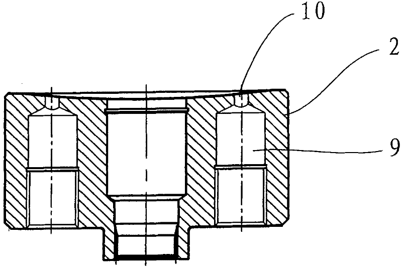
[0039] Image 6 , Figure 7 Shown is a structural diagram of Embodiment 1 of the double-row cylinder bore cylinder block of the present invention. In this embodiment, the number of waist-shaped through holes 23 in the double-row cylinder bore cylinder block 20 is equal to the two rows of cylinder bores 21, 22, that is, each cylinder hole 21 or 22 is correspondingly provided with a waist-shaped through hole 23, and the bottoms of the cylinder holes 21, 22 are provided with connecting holes 24, 25. The distribution positions of the waist-shaped through holes should correspond to the positions of the semicircular arc distribution holes on the distribution plate.

[0040]Usually, the diameters of the cylinder bores arranged on two circles with different radii are not equal, and the diameter of the cylinder bore 21 on the large diameter circle is greater than the diameter of the cylinder bore 22 on the small diameter circle. The waist-shaped through-holes 23 are evenly distribut...

Embodiment 2

[0044] Figure 8 , Figure 9 Shown is another embodiment of the structure of the cylinder 20' in the axial piston pump of the double-row cylinder bore cylinder of the present invention. The difference from Embodiment 1 is that the number of waist-shaped through holes 23' is equal to one row of cylinder bores The bottoms of adjacent cylinder holes 21', 22' on every two circumferences are provided with connecting holes 24' and 25' communicating with the same waist-shaped through hole 23'. Compared with the first embodiment, the advantage is that the number of waist-shaped through holes is reduced, and the processing man-hours are saved.


PUM


Abstract

The invention relates to an axial plunger pump, and in particular relates to an axial plunger pump with double rows of cylinder holes and cylinder bodies. The plunger pump comprises a driving main shaft, a cylinder body, a fluid distributor, a plunger, a swinging tray and an upper cover, wherein the cylinder bodies are provided with a plurality of cylinder holes; the fluid distributor is provided with two semi-circle fluid distribution holes; the plunger pump is characterized in that the plurality of cylinder holes in the cylinder bodies are divided into two rows; the numbers of the two rows of cylinder holes are equal, and are alternatively distributed on two circumferences with the same radius centering on the axis of the driving main shaft; the bottom part of each cylinder hole is provided with waist-shaped through holes which are communicated with the fluid distribution holes on the fluid distributor; and the waist-shaped through holes are all distributed on the circumferences with the same radius centering on the axis of the driving main shaft. Through the application of the cylinder bodies of the two rows plunger holes, the fluid pulsation can be reduced effectively, the stability of the pump operation can be improved, so that the aim of vibration and noise reduction is achieved; by adopting the cylinder bodies of the two rows of plunger holes, under the condition of increasing discharging amount without changing the integral structure of the pump, the integral structure is more compact; and the increase of the flow rate also enables the working range of the pump to be increased greatly.

Description

technical field [0001] The invention relates to an axial plunger pump, in particular to an axial plunger pump with a double-row cylinder bore cylinder body, which can increase the flow rate and reduce the pulsation coefficient. Background technique [0002] The structure of the existing direct shaft plunger pump is as follows: figure 1 , 2 As shown, it mainly includes a drive spindle 1, a cylinder body 2, a flow plate 3, a plunger 4, a swing plate 5, an upper cover 6, a swing plate angle adjustment device 7 and a sliding shoe 8, wherein the cylinder body 2 is provided with a row of The cylinder bores 9 (such as image 3 , Figure 4 As shown), the bottom of the cylinder bore is provided with a waist-shaped through hole 10 communicating with the valve plate. The plunger 4 is slidably disposed in the cylinder hole 9 and is slidably disposed on the swing plate 5 through a sliding shoe 8, and the swing plate 5 forms an inclination angle with the rotation axis of the cylinder...

Claims


Application Information

Patent Timeline
Patent Type & Authority Applications(China)
IPC IPC(8): F04B1/22F04B53/16
Inventor 杨广文周宇吕树平夏和平安建刚焦玲
Owner BEIJING HUADE HYDRAULIC INDAL GROUP
Why Eureka
Try Eureka