Gas-bag type band-type brake

A brake and airbag technology, applied in the field of components of the drive device, can solve the problems of increased operating cost, high noise, increased operating cost, etc., and achieve the effects of reducing maintenance cost, expanding the scope of application, and prolonging the service life

Inactive Publication Date: 2011-09-21
SHANGHAI CORAL TEXTILE MACHINERY
View PDF6 Cites 6 Cited by
  • Summary
  • Abstract
  • Description
  • Claims
  • Application Information

AI Technical Summary

Problems solved by technology

[0002] The driving devices of the yarn winding machine are all driven by electricity. The common braking method of the motor is electromagnetic brake. The main components of the brake mechanism include brake electromagnets and brake shoe brake components. The brake The electromagnet consists of three parts: iron core, armature and coil. The brake shoe brake components include brake wheel, brake shoe and spring, etc. The shaft extension of the brake wheel and the motor is coaxial. When running, the motor is powered on and brakes at the same time. The coil of the electromagnet is also energized, and its armature pulls in, and overcomes the spring tension of the brake member to separate the brake shoe and brake wheel of the brake, and drives the motor to run normally; when the machine stops, disconnect the switch or contactor of the power circuit, and the motor When the power is lost, the coil of the brake electromagnet is also powered off, and the armature is separated from the iron core under the action of the spring tension, and the brake shoe of the brake is tightly held by the brake wheel, and the motor is braked and stopped. Holding brake, its braking force is strong, safe and reliable, and will not cause accidents due to sudden power failure, but its electromagnetic brake has a large structure and high production cost. Due to its high operating speed, the impact force of the electromagnet is large , and directly acts on the braking mechanism, which is likely to cause loosening, damage or malfunction of the fasteners and cause failure. The noise is large, and it is difficult to form the gentle braking function required by the yarn winding machine. Due to the high braking speed, it is easy to Vibration and shock are generated, which affect the working life of the motor bearings. The related components are severely worn and must be replaced frequently, which increases the operating cost. In order to maintain the normal function of the brake, the brake clearance of the motor needs to be regularly maintained and adjusted, further increasing the operating cost.

Method used


Image

  • Gas-bag type band-type brake
  • Gas-bag type band-type brake
  • Gas-bag type band-type brake

Examples


Embodiment Construction

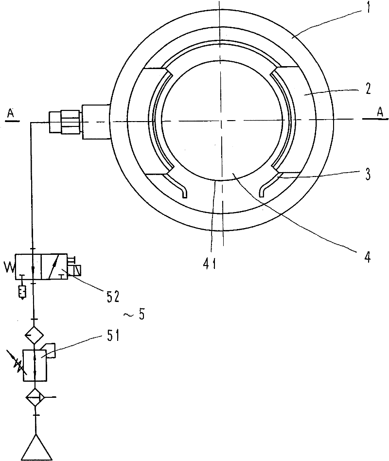
[0013] refer to figure 1 , the airbag type brake includes an airbag assembly 1, a friction plate 2, a return spring 3, a friction wheel 4 and a pneumatic control system 5.

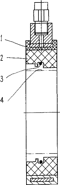
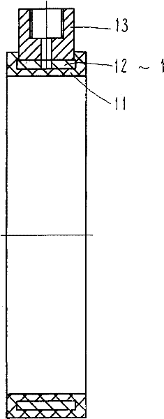
[0014] Air bag assembly 1, such as figure 1 , 2 , 3, and 4, the assembly includes a working chamber 10, an air bag 11, a retaining ring 12 and a joint 13, wherein:

[0015] Working chamber 10, such as Figure 4 As shown, it is composed of the inner annular surface 112 of the airbag 11, the left side wall 115, the right side wall 116 and the inner annular surface 121 of the stop ring 12. When the non-braking state, the working chamber 10 is only the inner annular surface 121 and the joint gap between the annulus 112 in the cavity;

[0016] The airbag 11 is an annular capsule with an inner cavity, which can be made of rubber or plastic, and its inner wall surface 111 is a circular through hole, and the inner wall surface 111 is the surface in contact with the friction plate 2. 112. The inner surface of ...


PUM


Abstract

The invention provides a gas-bag type band-type brake which mainly solves the technical problems that the structural size cannot be reduced, the braking performance cannot be improved and the like. The technical scheme is as follows: the brake is provided with a gas bag assembly, and the inner cavity of the gas bag assembly is provided with a baffle ring which is fixedly provided with a joint; the gas bag assembly is provided with a friction plate and a resetting spring is clamped at the inner side of the friction plate. In the invention, the gas-bag type band-type brake is suitable for braking each type of driving motor of a yarn winding machine.

Description

Technical field: [0001] The invention relates to a drive device for a yarn winding machine, in particular to a component of the drive device. Background technique: [0002] The driving devices of the yarn winding machine are all driven by electricity. The common braking method of the motor is electromagnetic brake. The main components of the brake mechanism include brake electromagnets and brake shoe brake components. The brake The electromagnet consists of three parts: iron core, armature and coil. The brake shoe brake components include brake wheel, brake shoe and spring, etc. The shaft extension of the brake wheel and the motor is coaxial. When running, the motor is powered on and brakes at the same time. The coil of the electromagnet is also energized, and its armature pulls in, and overcomes the spring tension of the brake member to separate the brake shoe and brake wheel of the brake, and drives the motor to run normally; when the machine stops, disconnect the switch o...

Claims


Application Information

Patent Timeline
Patent Type & Authority Applications(China)
IPC IPC(8): F16D49/06
Inventor 张天海张晖沈怡平黄立群霍文马许建钢袁建国陈向坤
Owner SHANGHAI CORAL TEXTILE MACHINERY
Why Eureka
Try Eureka