Laser reflector

A technology of laser reflection and laser, which is applied in the field of laser reflectors to achieve the effect of reducing spherical aberration and preventing damage

Inactive Publication Date: 2011-09-21
MITUTOYO CORP
View PDF6 Cites 2 Cited by
  • Summary
  • Abstract
  • Description
  • Claims
  • Application Information

AI Technical Summary

Problems solved by technology

The above-mentioned problems are not limited to laser interferometric length measuring instruments, but also coexist in precision measuring devices and precision processing devices that use lasers, and in laser reflectors that retroreflect laser light from irradiation parts installed in the devices.

Method used


Image

  • Laser reflector
  • Laser reflector
  • Laser reflector

Examples


no. 1 Embodiment approach

[0043] The structure of the laser interferometer

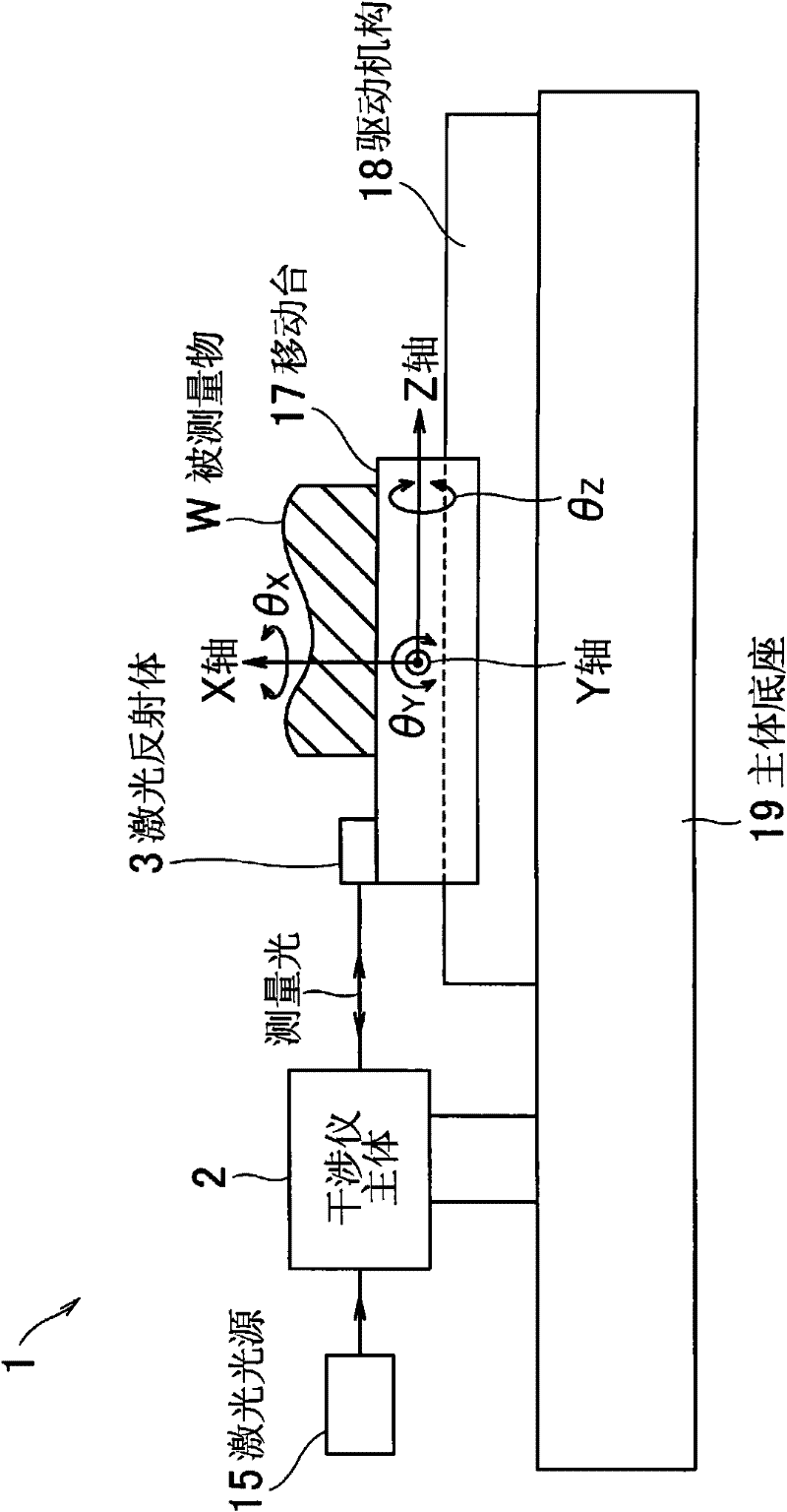
[0044] figure 1 It is a schematic configuration diagram showing the laser interferometric length measuring instrument according to the first embodiment of the present invention.

[0045] The laser interferometric length measuring instrument 1 of this embodiment has a main body base 19, a laser light source 15, an interferometer main body 2, a moving table 17 for placing the object W to be measured, a driving mechanism 18 of the moving table 17, and a Laser reflector 3 on top. In addition, the interferometer main body 2 functions as the irradiation means of the present invention.

[0046] The laser light source 15 is provided independently of the interferometer main body 2 , and supplies laser light of a predetermined wavelength (λ) to the interferometer main body 2 .

[0047] Interferometer main body 2 is fixed on the main body base 19, and Figure 11 Similarly, the conventional interferometers described in hereinafter h...

no. 2 Embodiment approach

[0079] Image 6 It is a cross-sectional view showing a laser reflector according to a second embodiment of the present invention. The laser interferometer 101 has substantially the same structure as above, but the structure of the laser reflector is different. Here, a description will be given using reference numerals obtained by adding 100 to the reference numerals of members different from the above. The laser reflector 103 includes a focal length f 2 A lens 105, a sphere 104 with a refractive index n2, and a housing 107. Set the center distance S between the lens 105 and the sphere 104 2 Or the focal length f of the lens 105 2 , so that the focal length f 2 Distance from center S 2 unanimous. The cladding body 12 covering a part of the surface of the sphere 104 is in the region of the hemispherical surface of the sphere 104 farther away from the lens 105 (away from the lens 105), at the intersection point (A) of the hemispherical surface and the optical axis (P axis)...

no. 3 Embodiment approach

[0090] Figure 9 It is a cross-sectional view showing a laser reflector according to a third embodiment of the present invention. The laser interferometer 201 has substantially the same structure as above, but the structure of the laser reflector is different. Here, a description will be given using reference numerals obtained by adding 200 to the reference numerals of members different from the above.

[0091] The laser reflector 203 includes a spherical body 204 having a refractive index n3 and a case 207 holding the spherical body 204 . A circular window 6 is formed on the casing 207 in the same manner as described above. In addition, a part of the surface of the spherical body 204 is covered with the covering body 12 in the same manner as above.

[0092] The sphere 204 is made of a special material with a refractive index n3 approximately 2 (n3≈2). Therefore, when the laser light 8 is incident on the sphere 204, it converges on a point on the surface of the sphere oppo...


PUM


Abstract

The present invention provides a laser reflector capable of always effectively returning the reflected laser beam in the direction parallel to an incident laser beam, comprising: a lens and a spherical body respectively provided on the optical axis (P-axis) of the laser beam; a coating that covers the surface of the spherical body and reflects the laser beam and a shell housing the above members. The laser is converged to one point by the lens and the spherical body, and reflected by the coating. The center and the focus (F1) of the lens are arranged on the P-axis and the center of the spherical body is arranged on the connection line for connecting the center of the lens and the focus (F1). The coating covers an area at least comprising the intersection (Q1) of the optical axis (P-axis) and a half spherical surface of the spherical body closer to the focus (F1) of the lens. The distance (S1) between the centers of the lens and the spherical body and the refractive index (n1) of the spherical body are set that: the laser from the lens converged to the focus (F1) is refracted by the spherical body and converged to the intersection (Q1) covered by the coating.

Description

technical field [0001] The present invention relates to a laser reflector that reflects laser light from an irradiating part toward the same irradiating part, and particularly relates to an improvement of a laser reflector used in a laser interferometric length measuring instrument. Background technique [0002] Conventionally, there has been known a laser interferometric length measuring instrument using a Michelson interferometer capable of measuring the size of an object to be measured with high resolution and without contact (for example, refer to Japanese Patent Application Laid-Open No. 2-115701). Such as Figure 11 As shown, the laser interferometric length measuring instrument described in the above-mentioned document has a laser light source 15, an interferometer main body 2, and a moving platform (not shown) on which the object to be measured is placed, and the laser light from the laser light source 15 is split by a beam splitter 21 Then, the measurement light is ...

Claims


Application Information

Patent Timeline
Patent Type & Authority Applications(China)
IPC IPC(8): G02B17/02G02B7/02G02B7/182G02B1/10G01B9/02
CPCG02B5/134
Inventor 谷村吉久
Owner MITUTOYO CORP
Why Eureka
Try Eureka