Electric lamp with an outer bulb and a built-in lamp and associated production method

An embedded, light bulb technology, applied in discharge lamps, circuits, incandescent lamps, etc., can solve problems such as complex mechanical technology, and achieve the effects of improving energy efficiency, reliable electrical contact, and reducing manufacturing costs

Inactive Publication Date: 2011-09-21
OSRAM GMBH
View PDF2 Cites 0 Cited by
  • Summary
  • Abstract
  • Description
  • Claims
  • Application Information

AI Technical Summary

Problems solved by technology

Here, complex mechanica

Method used


Image

  • Electric lamp with an outer bulb and a built-in lamp and associated production method
  • Electric lamp with an outer bulb and a built-in lamp and associated production method
  • Electric lamp with an outer bulb and a built-in lamp and associated production method

Examples


Embodiment Construction

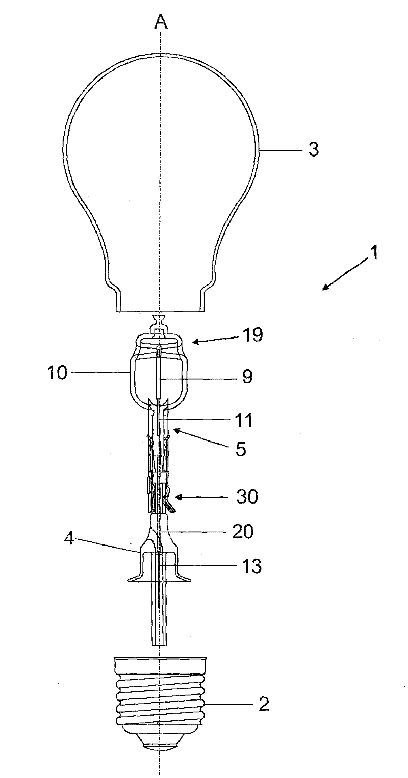
[0027] figure 1 The lamp 1 is shown in its entirety. The outer bulb 3 is held in a commercially available lamp cap 2 of type E27, which has a ceramic base or lamp support and a screw portion fixed thereto. A built-in lamp 19 is arranged in the outer bulb 3 . The built-in lamps are designed as so-called high-voltage halogen incandescent lamps and as lamps known from the prior art. The lamp 1 has a longitudinal axis A. As shown in FIG.

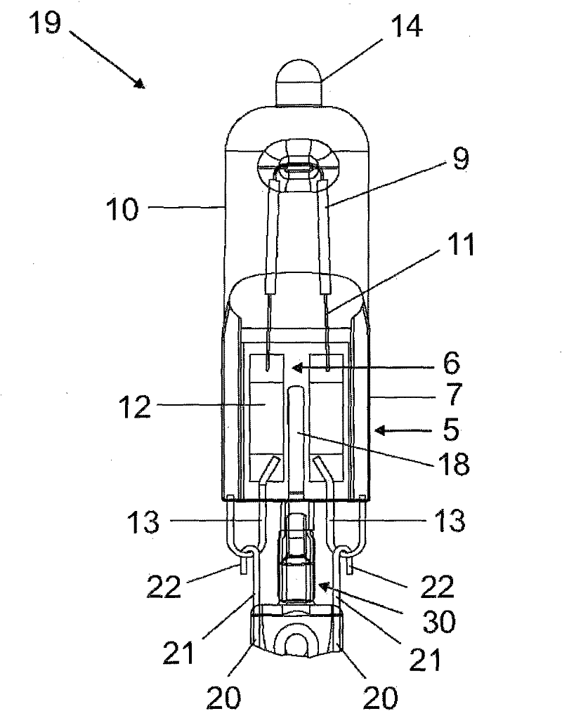
[0028] Recessed light 19 (see also figure 2 with 3 ) is equipped with a single extrusion 5 with two broad sides 6 and two narrow sides 7 . A pin-shaped external power supply line 13 protrudes from the pinch 5 . These external supply lines are bent back in a U-shape on the narrow side of the pinch 5 .

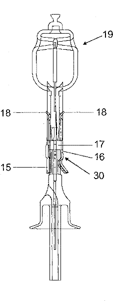
[0029] The built-in lamp 19 is, for example, a one-sided extruded halogen incandescent lamp with the lamp vessel 10 . The illuminant 9 is electrically conductively connected to the base 2 via a power supply line system. The power supply ...


PUM


Abstract

The invention discloses a built-in lamp with a bulb having a press section, wherein the bulb is kept in a plate-like stand of the outer bulb by a mounting clip. The electric connection is realized in the way that an outer power supply line of the built-in lamp are bent back in the form of a bow and a lead is in the form of a ring for keeping the bow. In addition, the invention also relates to a production method of the electric lamp.

Description

technical field [0001] The invention is based on a lamp according to the preamble of claim 1 . In particular, the invention relates to an electric lamp with a base, in particular a lamp formed from a built-in lamp arranged in an outer bulb, wherein the base is electrically conductively connected to a power supply line. In particular, the invention relates to a one-sided capped electric lamp having an outer bulb held in the base and at least one recessed lamp arranged in the outer bulb. Such halogen incandescent lamps are especially designed for operation at high voltages (HV), typically 100V to 250V. Background technique [0002] WO-A 2009156251 discloses a holding device for a built-in lamp in an outer bulb, wherein the holding device has a metal mounting clip placed on a disc-shaped bottom. [0003] In this case, the external power supply line protruding from the built-in lamp is usually firmly connected to the lead line protruding from the plate-shaped base for locking....

Claims


Application Information

Patent Timeline
IPC IPC(8): H01K1/40H01K1/38H01K3/12
CPCH01K1/40H01K1/46H01K1/34Y02B20/125H01J5/62Y10T29/49002Y02B20/00
Inventor 罗兰·贝希特埃里克·科恩多弗
Owner OSRAM GMBH
Why Eureka
Try Eureka