
Multi-input multi-output beamforming system and data sending method thereof

A data transmission method and beamforming technology, applied in the field of wireless communication, can solve the problem of not being able to choose the best data transmission method, etc.

Inactive Publication Date: 2011-09-21
ZTE CORP
View PDF7 Cites 5 Cited by
  • Summary
  • Abstract
  • Description
  • Claims
  • Application Information

AI Technical Summary

Problems solved by technology

[0011] The main purpose of the present invention is to provide a multiple-input multiple-output beamforming system and its data transmission method, to solve the problem in the above-mentioned related technologies that the best data transmission method cannot be selected according to the real-time changes of mobile and wireless channels

Method used


Image

  • Multi-input multi-output beamforming system and data sending method thereof
  • Multi-input multi-output beamforming system and data sending method thereof
  • Multi-input multi-output beamforming system and data sending method thereof

Examples


Embodiment 2

[0177] Implement columns using spatial correlation alone.

[0178] The sender presets the condition number threshold K c and proportional threshold T r . All receiving ends of its service are processed as follows.

[0179] The sender presets the condition number threshold K c and proportional threshold T r . Assume that the channel matrix H corresponding to subcarrier k is calculated k The condition number is K k ,k=1,...,N c , N c is the carrier number of the carrier set used for decision;

[0180] Compare K k and threshold K c , if K k ≥K c , SMBF_Num=SMBF_Num+1, otherwise, SMBF_Num remains unchanged.

[0181] Here, the condition number is preferably defined as K k = λ min k λ max k , or K k = λ min k × ...

Embodiment 3

[0186] The combination method is CINR in CQI, and SD_TH CQI 1 = SD_TH CQI 2 = SM_TH CQI 1 = SM_TH CQI 2 = Examples of THCINR.

[0187] The sender processes all receivers it serves as follows.

[0188] Calculate the CINR in the data transmission mode currently used by the receiving end, compare CINR and THCINR, if CINR≤THCINR, select the spatial diversity beamforming mode, otherwise select the spatial multiplexing beamforming mode.

[0189] Send the receiver's data with the selected data sending mode.

Embodiment 4

[0191] The combination method is DIUC in CQI, and SD_TH CQI 1 = SD_TH CQI 2 = SM_TH CQI 1 = SM_TH CQI 2 = Example of THDIUC.

[0192] The sender processes all receivers it serves as follows.

[0193] Calculate the CINR in the data transmission mode currently used by the receiving end, and look up the table to find the corresponding DIUC, compare DIUC and THDIUC, if DIUC≤THDIUC, select the spatial diversity beamforming mode, otherwise select the spatial multiplexing beamforming mode.

[0194] Send the receiver's data with the selected data sending mode.


PUM


Abstract

The invention discloses a multi-input multi-output beamforming system and a data sending method thereof, and the method comprises the following steps: the acquiring step: acquiring channel quality information (CQI) of the multi-input multi-output beamforming system; the determining step: determining that space diversity beamforming mode or space multiplexing beamforming mode is better according to the CQI; and the switching step: switching the existing data sending way to the better space diversity beamforming mode or the space multiplexing beamforming mode. By selecting the space diversity beamforming mode or the space multiplexing beamforming mode according to the CQI, the switching to the space diversity beamforming mode or the space multiplexing beamforming mode is further realized, so that the space diversity beamforming mode and the space multiplexing beamforming mode are effectively combined, and the performances of the system are improved to the greatest extent.

Description

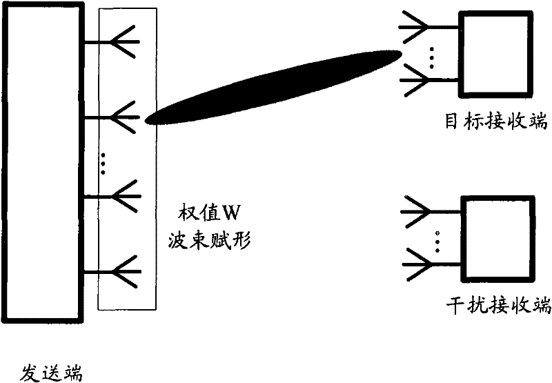
technical field [0001] The invention relates to the field of wireless communication, in particular to a multiple-input multiple-output beamforming system and a data sending method thereof. Background technique [0002] Beamforming (Beamforming, referred to as BF) is based on the principle of adaptive antennas. The antenna array is used to weight each antenna unit through an advanced signal processing algorithm, so that the array is aligned in the direction of the useful signal in real time, and the null point is formed in the interference direction. Suppress interference signals, thereby improving signal-to-interference-noise ratio, improving system performance, and increasing system coverage. [0003] figure 1 It is a schematic diagram of beamforming according to the related technology. There are multiple antennas at the sending end. The data of the source is modulated by channel coding, multiplied by the weight W on the corresponding antenna, and then sent out to form a b...

Claims


Application Information

Patent Timeline
Patent Type & Authority Applications(China)
IPC IPC(8): H04B7/06H04L1/00
CPCH04B7/0632H04B7/0689H04B7/0697H04B7/0617H04B7/0413
Inventor 肖华华鲁照华张万帅
Owner ZTE CORP
Learn More