Casting method and casting mold of vertical lathe ram

A casting mold and ram technology, which is applied to casting molding equipment, casting molds, casting mold components, etc., can solve the problem that forging blanks cannot make intermediate holes, etc., so as to shorten the production cycle, reduce energy consumption and pollution, and shorten the processing cycle. Effect

Inactive Publication Date: 2014-10-29
衡阳中钢衡重铸锻有限公司
View PDF5 Cites 0 Cited by
  • Summary
  • Abstract
  • Description
  • Claims
  • Application Information

AI Technical Summary

Problems solved by technology

[0003] The purpose of the present invention is to overcome the above-mentioned deficiencies of the prior art and provide a casting mold for a vertical lathe ram, which can realize sequential cold shrinkage when casting a vertical lathe ram, solve the difficult problem that the forging blank cannot manufacture the middle hole, and save cost

Method used


Image

  • Casting method and casting mold of vertical lathe ram
  • Casting method and casting mold of vertical lathe ram
  • Casting method and casting mold of vertical lathe ram

Examples


Embodiment 1

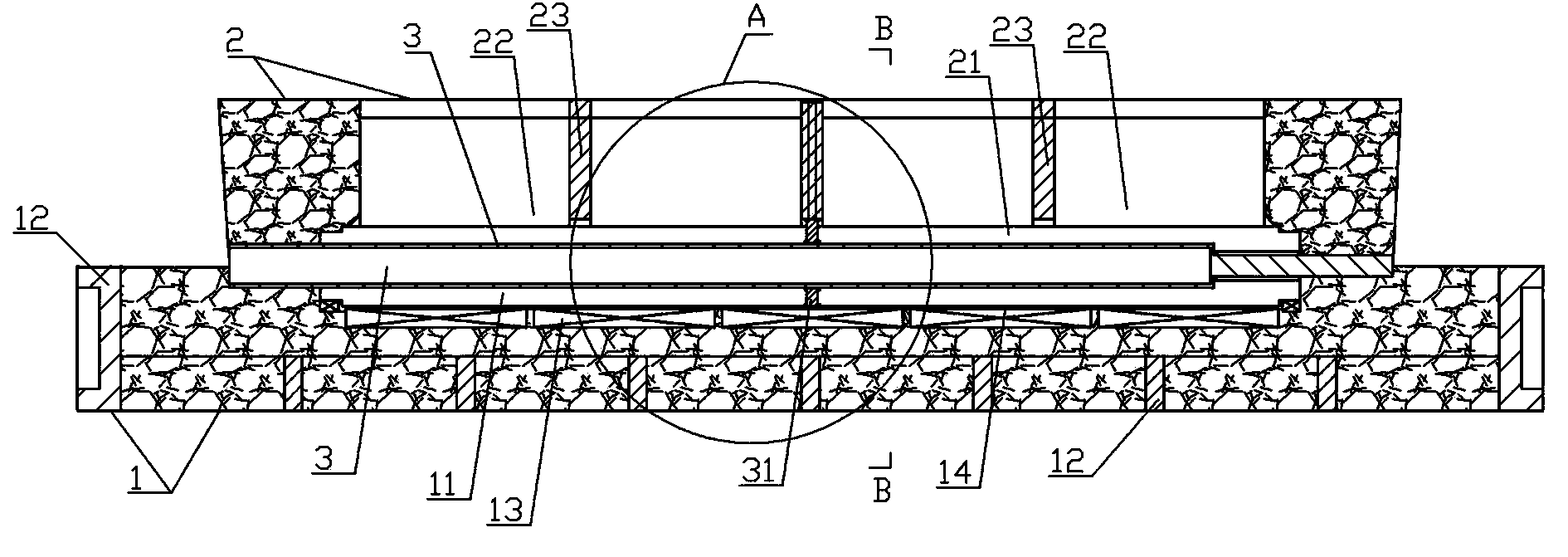
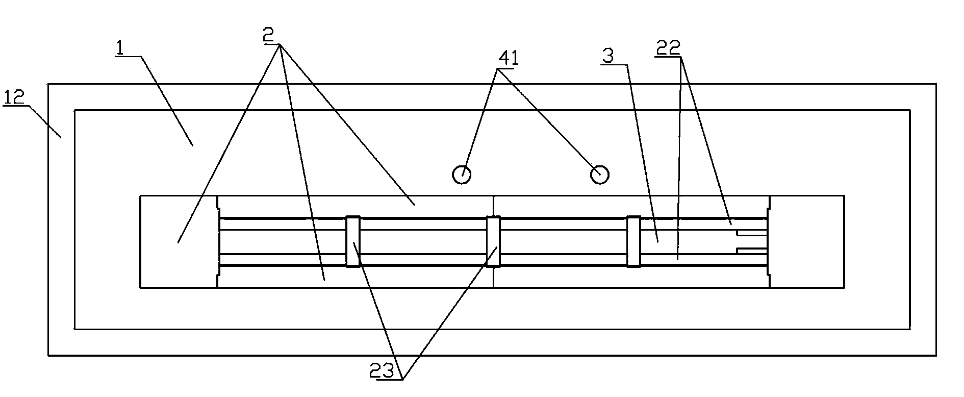
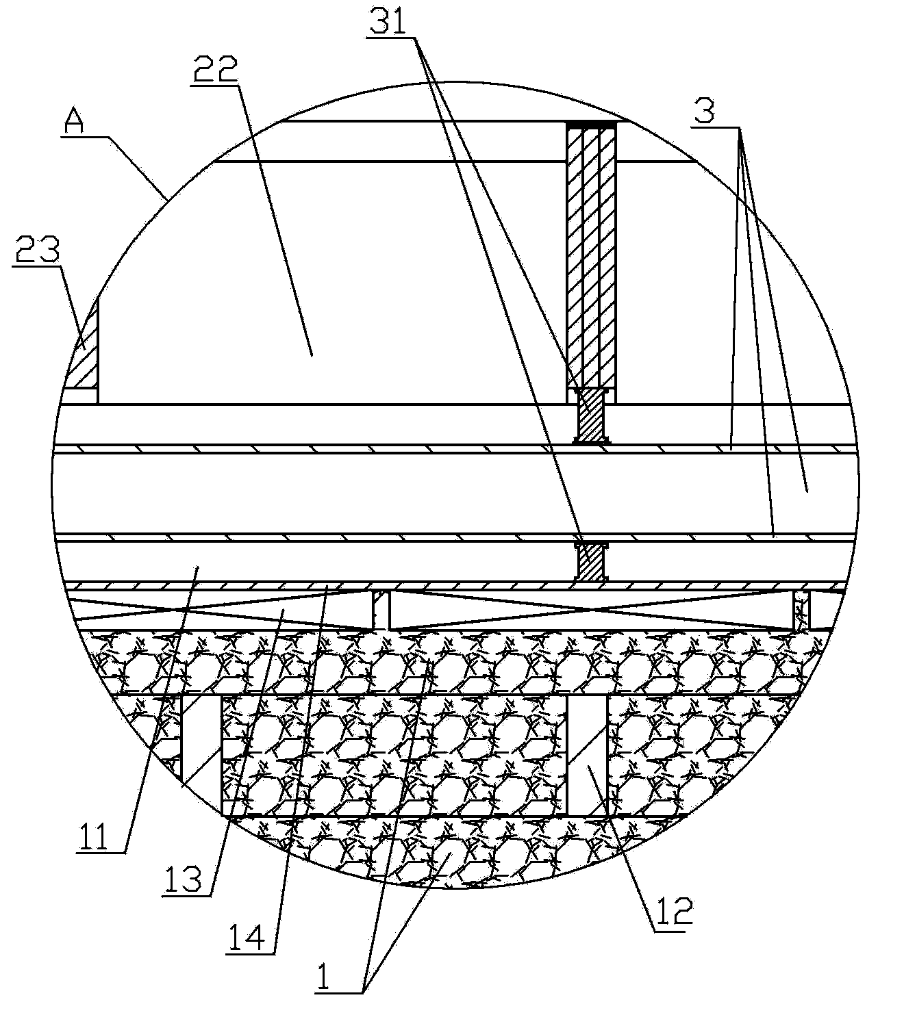
[0077] The material is ZG35CrMo, the size of the part is 350×350×4150, the weight of the casting is 3250kg, and the total pouring weight is 6600kg; when casting, the parting surface of the ram is divided into upper and lower parts, and each parting surface has a parting negative number. Sufficient processing allowance is left on the processing surface, and the casting shrinkage is 1.8%; the sprue 41, runner 42 and ingate 43 are wrapped with organic ester water glass quick-drying sand to prevent water from running out, and the sprue 41 is 2 channels of φ80, runner 42 is one of φ80, and ingate 43 is 4 channels of φ60 evenly distributed to ensure that the gating system is completely open; the metal cooling layer 13 is made of special material ZG270~500, and the sand layer 14 is made of resin sand. The sand thickness is 30~40mm, the distance between the metal blocks of the metal cooling layer 13 is not more than 30mm; the width of the bottom of the riser mouth is equal to the width...

Embodiment 2

[0079] The material is ZG35CrMo, the part size is 220×220×2710, the casting weight is 935kg, the total pouring weight is 1840kg, and the pouring temperature is 1560°C; when casting, the parting surface of the ram is divided into upper and lower parts, and each parting surface has a parting negative number. Sufficient processing allowance is left on the processing surface, and the casting shrinkage is 1.8%; the sprue 41, runner 42 and ingate 43 are wrapped with organic ester water glass quick-drying sand to prevent water from running out, and the sprue 41 is 2 channels of φ80, runner 42 is one of φ80, and ingate 43 is 4 channels of φ60 evenly distributed to ensure that the gating system is completely open; the metal cooling layer 13 is made of special material ZG270~500, and the sand layer 14 is made of resin sand. The sand thickness is 30~40mm, the distance between the metal blocks of the metal cooling layer 13 is no more than 30mm; the width of the bottom of the riser mouth is...


PUM

PropertyMeasurementUnit
heightaaaaaaaaaa
widthaaaaaaaaaa
thicknessaaaaaaaaaa

Abstract

The invention discloses a method for casting a vertical lathe ram and a casting die. The casting die comprises a ram exterior lower sand die (1), a ram exterior upper sand die (2), a ram core type die (3) and a pouring system; the ram exterior upper sand die (2) is installed above the ram exterior lower sand die (1); a cavity of which the appearance is in consistence with the appearance of the vertical lathe ram to be cast is formed between the ram exterior upper sand die (2) and the ram exterior lower sand die (1); a raiser cavity (22) is formed outside the ram exterior upper sand die (2); the ram core type die (3) is arranged in the cavity formed by the ram exterior lower sand die (1) and the ram exterior upper sand die (2); and the pouring system is a pouring pipeline system and is connected between a ram external lower cavity (11) of the ram exterior lower sand die (1) and the outside. The casting method comprises the following steps of: producing die samples and die boxes, producing the casting die, pouring, precisely processing and the like. According to the invention, the cast vertical lathe ram is used to replace the forged vertical lathe ram, and the production cost is saved.

Description

technical field [0001] The invention relates to a manufacturing method and special equipment for a vertical lathe ram, in particular to a casting method and a casting mold for a vertical lathe ram. Background technique [0002] The ram is a convoluted casting, the casting itself has no end zone, the wall thickness of the main body is uniform, there is not enough temperature gradient to achieve sequential solidification, and shrinkage defects are prone to occur at the bottom of the casting. The ram is an important load-bearing part of the vertical lathe, which is related to the machining accuracy of a vertical lathe, the service life and safety of the vertical lathe. The overall quality requirements of the ram are very high. Ultrasonic flaw detection is required to meet the requirements of the national standard GB7233-87 Level I or above, and the magnetic particle flaw detection inspection meets the national standard GB9444-87 Level I or above. However, large-scale vertical ...

Claims


Application Information

Patent Timeline
Patent Type & Authority Patents(China)
IPC IPC(8): B22C9/22B22C9/08
Inventor 谢驰中刘友成文建华杨斌王惠民
Owner 衡阳中钢衡重铸锻有限公司
Why Eureka
Try Eureka