
Precision detection method for numerical control machine based on laser-tracking combined measurement

A CNC machine tool and laser tracking technology, which is applied to measuring devices, optical devices, instruments, etc., can solve the problems of increasing uncertainty in angle measurement, affecting the overall accuracy of spatial coordinates, and difficult to accurately measure angles.

Inactive Publication Date: 2011-09-28
XI AN JIAOTONG UNIV
View PDF3 Cites 26 Cited by
  • Summary
  • Abstract
  • Description
  • Claims
  • Application Information

AI Technical Summary

Problems solved by technology

At present, some countries have applied laser trackers to the field of machine tool accuracy detection. Although my country also uses laser trackers to measure the accuracy of machine tools, most of them are directly measured by single-station method. Due to the limited measurement accuracy of the corner and the angle measurement itself Measurement uncertainty increases with distance
At the same time, due to the influence of the atmospheric refractive index, the angle itself is difficult to measure accurately, which is far from the measurement accuracy of laser interference, which affects the overall accuracy of space coordinates. When testing high-precision CNC machine tools, the measurement accuracy cannot be guaranteed.

Method used


Image

  • Precision detection method for numerical control machine based on laser-tracking combined measurement
  • Precision detection method for numerical control machine based on laser-tracking combined measurement
  • Precision detection method for numerical control machine based on laser-tracking combined measurement

Examples


Embodiment Construction

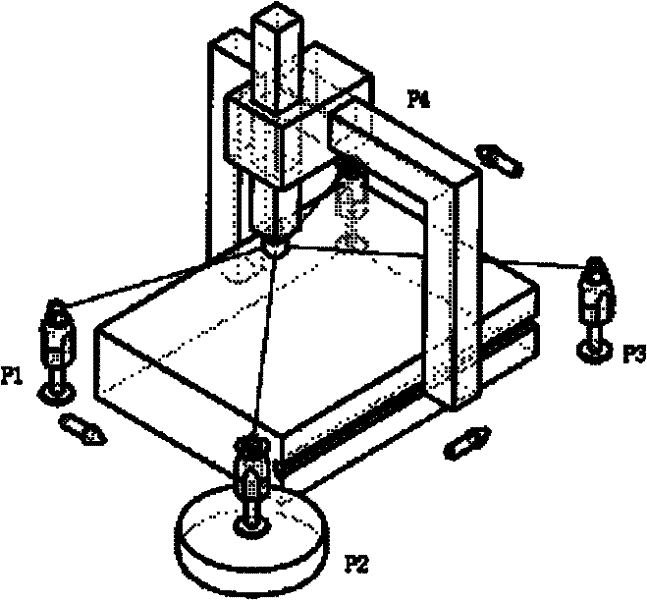
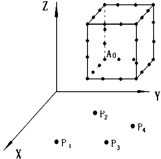
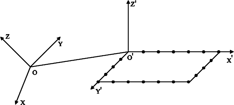
[0058] Such as figure 1 , figure 2 Shown: A method for detecting the accuracy of CNC machine tools based on laser tracking compound measurement, including the following steps:

[0059] (1) Multi-channel time-sharing measurement steps

[0060] During the measurement, the CNC machine tool is controlled to feed in three-dimensional space, and 32 measurement points are set on its motion path. A laser tracker measures the same motion trajectory of the CNC machine tool at least three base stations successively. When the CNC machine tool When the machine tool moves to the position of each measurement point, the CNC machine tool stops moving, and the distance measurement data and angle measurement data of the laser tracker at the position of the measurement point are recorded. After the measurement of all measurement points is completed, the laser tracker at different measurement points is obtained. The measurement data; during the measurement process, the number of measurement poi...


PUM


Abstract

The invention discloses a precision detection method for a numerical control machine based on laser-tracking combined measurement. According to the method, a numerical control machine is fed along the pre-set route in a three-dimensional space or a two-dimensional plane, and a laser tracker is operated to measure the same motion trace of the numerical control machine at three positions at least successively. The motion error at each measurement position can be known by processing the measurement data. During the measurement, the point coordinates measured by the laser tracker is taken as parameters to determine the initial position of the base station in which the laser tracker is located, and then the measurements made by the laser tracker is used to determine the spatial location of the base station, and finally the spatial coordinates of each measurement point is determined. in the invention, the problem that the initial position of the base station is difficult to determine is solved, the method in the invention improves the reliability and calculation efficiency for determining the bas station and measurement points. In addition, the method has the advantages of speediness and high precision and the like, and is capable of meeting the precision requirements of various of numerical control machines.

Description

technical field [0001] The invention relates to the technical field of laser precision measurement, in particular to a method for detecting the precision of a numerically controlled machine tool based on laser tracking compound measurement. Background technique [0002] The accuracy and precision stability of machine tools are important technical indicators of machine tools. Simply relying on improving the level of parts design, manufacturing and assembly to improve the machining accuracy of machine tools is expensive or even difficult to achieve. Fast and accurate measurement and compensation of machine tool system errors has become one of the important ways to improve the machining accuracy of machine tools. [0003] There are many factors that affect the machining accuracy of machine tools, such as geometric errors, force deformation errors, thermal deformation errors, dynamic errors, etc. Among them, geometric errors have the greatest impact on the machining accuracy of...

Claims


Application Information

Patent Timeline
IPC IPC(8): G01B11/00
Inventor 郭俊杰王金栋费致根邓玉芬贾天玖
Owner XI AN JIAOTONG UNIV
Learn More