
Method for calibrating triangle scanning deviations in light beam acquiring system based on target reflection signals

A technology of reflected signals and calibration methods, applied in optics, optical components, telescopes, etc., can solve the problem that the convergence speed of the algorithm cannot be guaranteed, and achieve the effect of improving real-time performance and controllability, shortening deviation correction time, and improving real-time performance.

Active Publication Date: 2012-10-10
INST OF OPTICS & ELECTRONICS - CHINESE ACAD OF SCI
View PDF0 Cites 0 Cited by
  • Summary
  • Abstract
  • Description
  • Claims
  • Application Information

AI Technical Summary

Problems solved by technology

Similarly, since this random movement has no certain regularity, and the average intensity statistics of the light intensity signal at each position requires a large number of signal samples, the convergence speed of the entire algorithm cannot be guaranteed

Method used


Image

  • Method for calibrating triangle scanning deviations in light beam acquiring system based on target reflection signals
  • Method for calibrating triangle scanning deviations in light beam acquiring system based on target reflection signals
  • Method for calibrating triangle scanning deviations in light beam acquiring system based on target reflection signals

Examples


Embodiment Construction

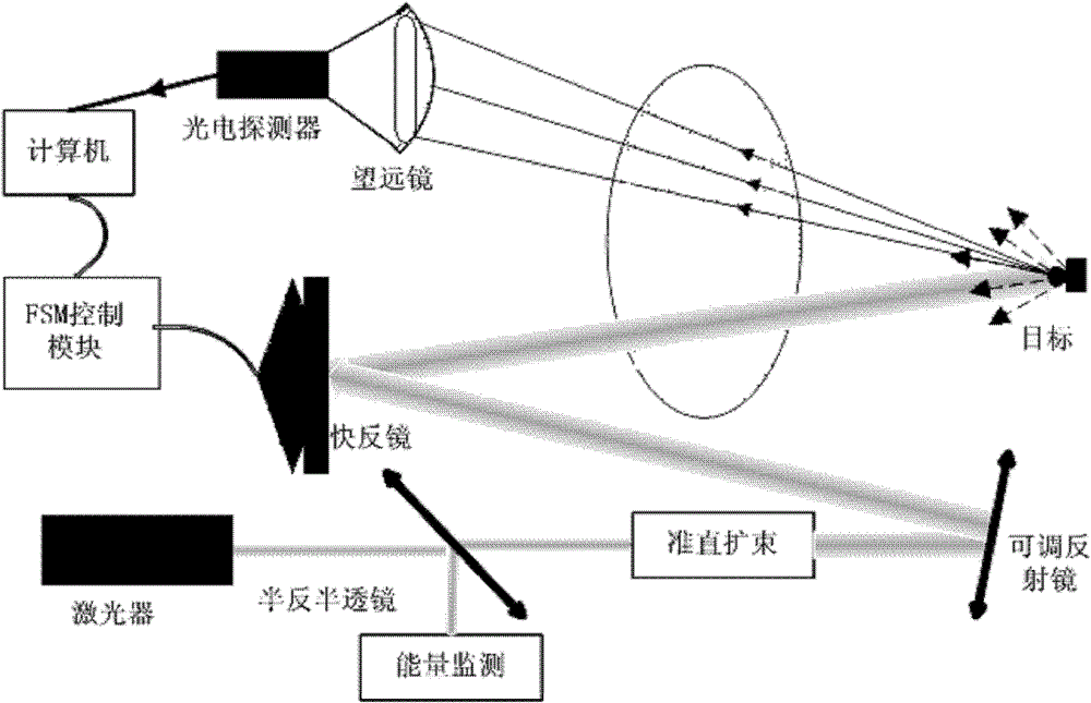
[0040] The beam aiming system used in the present invention is as figure 1 Shown: The Gaussian beam output by the laser is collimated and expanded to point to the space target through the control of the fast reflector, and the optical signal reflected from the target is received by the telescope, converted by the photoelectric detector and digitized by the data acquisition system, and input into the computer The aiming error estimation module estimates the deviation of the target relative to the statistical center of the beam, and inputs the deviation signal into the controller to drive the fast mirror to deflect and calibrate the beam deviation to form a closed-loop aiming system for aiming control; and it is set in the whole aiming process In , the position of the target remains unchanged relative to the aiming field of view, or the target is in the fine tracking state of the aiming system.

[0041] The beam aiming system involved in the present invention is established as ...


PUM


Abstract

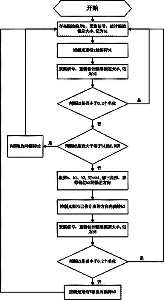
The invention discloses a method for calibrating triangle scanning deviations in a light beam acquiring system based on target reflection signals, and the method comprises the following steps: (1) in the process of carrying out light beam acquiring, because a target has a deviation b relative to a light beam statistics center, acquiring target reflection signals, and estimating the size of the deviation, and recording the deviation as b1; (2) driving a rapid reflector by virtue of an acquiring system, so that a light beam carries out a deviation b1 along a positive axis x; (3) acquiring signals, estimating a deviation, and recording the deviation as b2; (4) if a light beam acquiring operation is implemented, executing the step 1; if b2 is greater than 1.9 times of b1, executing a step 5; otherwise, executing a step 6; (5) controlling the light beam to carry out a negative deviation b2 along the positive axis x; (6) according to b, b1 and b2, calculating the direction of the deviation b2; (7) controlling the light beam to carry out a deviation b2 along the estimated direction; (8) acquiring signals, estimating a deviation, and recording the deviation as b3; (9) if the light beam acquiring operation is performed, executing the step 1; otherwise, executing a step 10; and (10) controlling the light beam to carry out a negative deviation b3 along an axis y, and then executing the step 1. By using the method disclosed by the invention, the automatic light beam acquiring is realized, the signal acquisition amount is reduced, and the deviation calibration time is shortened.

Description

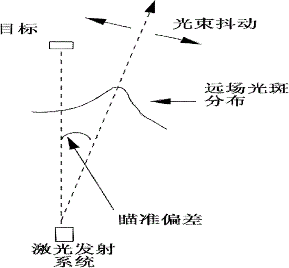
technical field [0001] The invention belongs to the field of beam control, and in particular relates to a method for calibrating triangular scanning deviation in a beam aiming system based on a target reflection signal, which is used to realize real-time closed-loop aiming of a beam at a target. Background technique [0002] Laser targeting systems play a key role in many areas such as active tracking, target illumination, and free-space communications. But as the beam travels through the atmosphere, random errors and deviations due to mechanical vibrations, atmospheric turbulence, and tracker limitations, as well as optical misalignment, can lead to off-axis aiming and loss of signal to the target. In most laser control systems, two kinds of aiming errors often appear, namely alignment error (static deviation of aiming) and beam jitter (temporary random error), such as figure 2 shown. [0003] In the early 1990s, a new estimation technique was proposed by Lukesh et al.: t...

Claims


Application Information

Patent Timeline
Patent Type & Authority Patents(China)
IPC IPC(8): G02B23/00G02B26/10
Inventor 周磊任戈谭毅
Owner INST OF OPTICS & ELECTRONICS - CHINESE ACAD OF SCI
Learn More