
Energy storage device and manufacturing method thereof

A technology of electric storage device and manufacturing method, which is applied in the direction of electrode manufacturing, secondary battery manufacturing, non-aqueous electrolyte storage battery electrodes, etc., and can solve problems such as circuit error operation and circuit damage

Inactive Publication Date: 2011-09-28
SEMICON ENERGY LAB CO LTD
View PDF4 Cites 0 Cited by
  • Summary
  • Abstract
  • Description
  • Claims
  • Application Information

AI Technical Summary

Problems solved by technology

[0006] When the above-mentioned electric storage device is discharged, in the circuit that becomes the load, when the supplied voltage changes, the circuit may be damaged or the circuit may malfunction.

Method used


Image

  • Energy storage device and manufacturing method thereof
  • Energy storage device and manufacturing method thereof
  • Energy storage device and manufacturing method thereof

Examples


Embodiment approach 1

[0027] In this embodiment, the charge and discharge characteristics of the power storage device will be described.

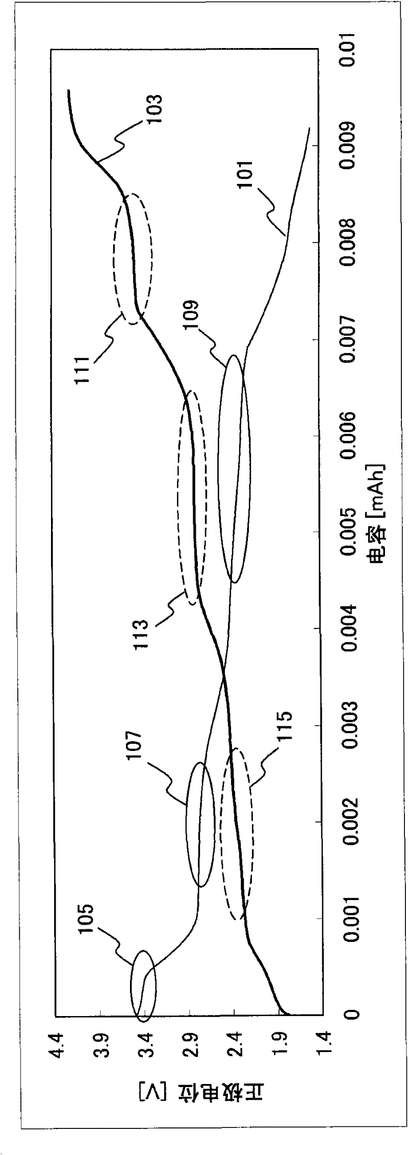
[0028] figure 1 The charge and discharge characteristics of the positive electrode of the power storage device are shown, and a discharge curve 101 and a charge curve 103 are shown. The horizontal axis represents capacitance, and the vertical axis represents positive electrode potential.

[0029] exist figure 1 Among them, since the discharge curve 101 has a potential flat portion (hereinafter also referred to as a plateau), a stable voltage can be supplied. and, in figure 1 The example in has three stages of platforms (platform 105, platform 107, platform 109).

[0030] Furthermore, as the positive electrode potentials of each plateau in the discharge curve 101, the potential Vmax of the plateau 105=3.5V, the potential Vmid of the plateau 107=2.9V, and the potential Vmin of the plateau 109=2.4V.

[0031] Since the discharge curve 101 has three stages of pl...

Embodiment approach 2

[0045] In this embodiment, an example of a method of manufacturing an electrical storage device capable of realizing the charge-discharge characteristics described in Embodiment 1 will be described.

[0046] Figure 2A to Figure 2C It is an example of the manufacturing method of the positive electrode of a lithium secondary battery.

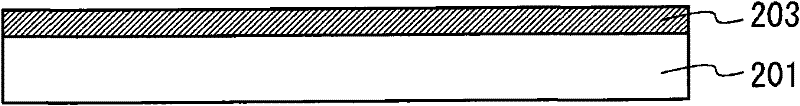
[0047] First, the current collector 201 ( Figure 2A ).

[0048] The material of current collector 201 is not particularly limited, and highly conductive materials such as platinum, aluminum, copper, and titanium can be used. Titanium is used in this embodiment.

[0049] Next, a film 203 containing an active material is formed on the current collector 201 ( Figure 2B ).

[0050] As the active material contained in the active material-containing film 203, lithium oxide is preferably used. Since lithium has a large ionization tendency and a small atomic radius, it can be stably inserted into and detached from the positive electrode. Thereby...

Embodiment approach 3

[0061] In this embodiment, an example of the configuration of the power storage device will be described.

[0062] use Figure 2C An example of the structure of the positive electrode used in the power storage device will be described.

[0063] The positive electrode 205 includes a current collector 201 and an active material-containing film 203 formed on the current collector 201 .

[0064] As the material of current collector 201 , the materials described in Embodiment Mode 2 can be used. Titanium is used in this embodiment.

[0065] As the material of the active material, the materials described in Embodiment Mode 2 can be used. In this embodiment, lithium iron phosphate with a thickness of 100 nm is used.

[0066] Next, an example of the structure of a power storage device using the above-mentioned positive electrode will be described.

[0067] Figure 3A to Figure 3C This is an example of the structure of an electrical storage device including a positive electrode 2...


PUM

PropertyMeasurementUnit
thicknessaaaaaaaaaa
thicknessaaaaaaaaaa
thicknessaaaaaaaaaa

Abstract

An object is to provide an energy storage device capable of supplying stable voltage and easily detecting remaining capacity and charging capacity. The energy storage device includes a positive electrode, a negative electrode formed so as to face the positive electrode, and an electrolyte interposed between the positive electrode and the negative electrode, in which a discharging curve or a charging curve of the positive electrode has plateaus (also referred to as flat portions of the potential). Specifically, the discharging curve or the charging curve of the positive electrode has a plurality of plateaus, and positive electrode potential can be monitored in plural steps, whereby the remaining capacity and the charging capacity can be easily detected.

Description

technical field [0001] The present invention relates to an electrical storage device and a method for manufacturing the electrical storage device. Background technique [0002] Due to increasing interest in environmental issues, the development of power storage devices such as secondary batteries and electric double layer capacitors used as power sources for hybrid vehicles has been intensified. Lithium-ion batteries and lithium-ion capacitors with high energy performance are attracting attention as candidates thereof. Since even a small lithium-ion battery can store a large amount of electricity, it has been installed in portable information terminals such as mobile phones and notebook personal computers, thereby achieving miniaturization of products. [0003] In secondary batteries and electric double layer capacitors, an electrolyte is interposed between a positive electrode and a negative electrode. It is known that both the positive electrode and the negative electrod...

Claims


Application Information

Patent Timeline
Patent Type & Authority Applications(China)
IPC IPC(8): H01M10/48H01M10/04H01M4/136H01M4/1397H01M4/02H01M4/13H01M4/36H01M10/052
CPCY02E60/12Y02E60/124H01M4/5825H01M4/0471H01M10/0562H01M4/0426Y02E60/122H01M10/0585H01M10/0525H01M4/1397H01M4/136H01M10/482Y10T29/49108Y10T29/49115Y02E60/10Y02P70/50
Inventor 汤川干央
Owner SEMICON ENERGY LAB CO LTD
Learn More