Hermetically sealed battery and method for manufacturing the same

A manufacturing method and airtight technology, applied in the field of joint structure, can solve the problems of severe electrode loss and difficult long-term stable welding, and achieve the effect of suppressing and reducing the occurrence of spatter

Inactive Publication Date: 2011-09-28
PANASONIC CORP
View PDF5 Cites 6 Cited by
  • Summary
  • Abstract
  • Description
  • Claims
  • Application Information

AI Technical Summary

Problems solved by technology

In this case, the welding of the lead wire and the sealing plate becomes the connection between aluminum, but generally speaking, aluminum has higher electrical conductivity and thermal conductivity than steel, and a large current must be passed for a short time during resistance welding. Compared with the welding of steel, the wear of the electrode used in resistance welding is severe, and it is difficult to perform long-term stable welding

Method used


Image

  • Hermetically sealed battery and method for manufacturing the same
  • Hermetically sealed battery and method for manufacturing the same
  • Hermetically sealed battery and method for manufacturing the same

Examples


Embodiment 1

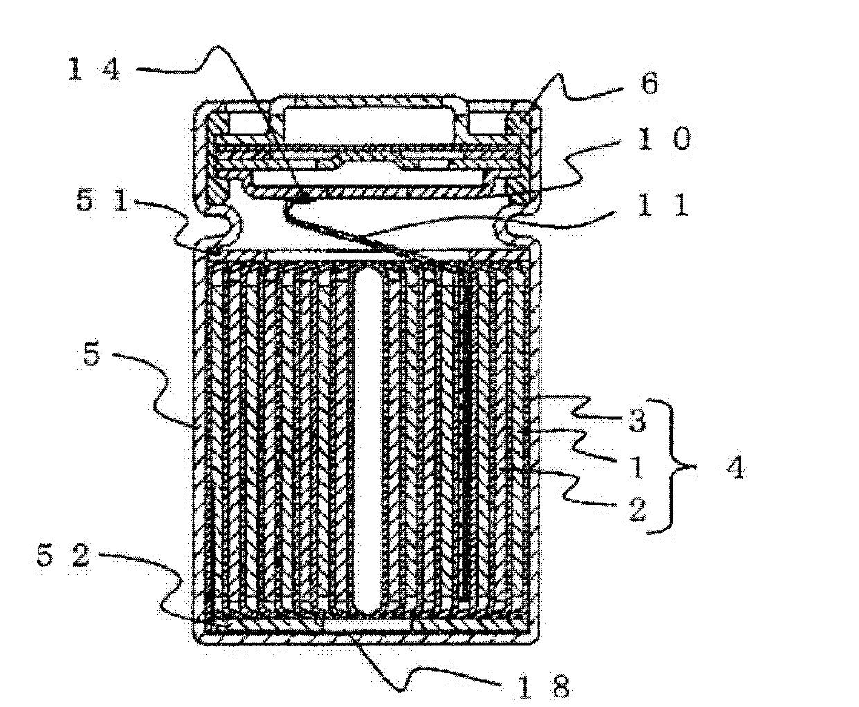
[0075] The positive electrode plate 1 was produced by the following method. First, use a kneader to mix 100 parts by weight of lithium cobaltate as an active material, 2 parts by weight of acetylene black as a conductive material, 2 parts by weight of polyvinylidene fluoride (PVdF) as a binder material, and an appropriate amount of N-methyl 2-Pyrrolidone is stirred together to produce a positive electrode mixture coating. Next, the positive electrode mixture paint was coated on both sides of a positive electrode current collector made of aluminum foil with a thickness of 15 μm, dried, pressed to make the total thickness 165 μm, and then longitudinally sheared to produce the positive electrode plate 1. .

[0076] In addition, the negative electrode plate 2 was produced by the following method. First, 100 parts by weight of artificial graphite as an active material, 2.5 parts by weight of a styrene-butadiene copolymer rubber particle dispersion (solid content of 40% by weight)...

Embodiment 2

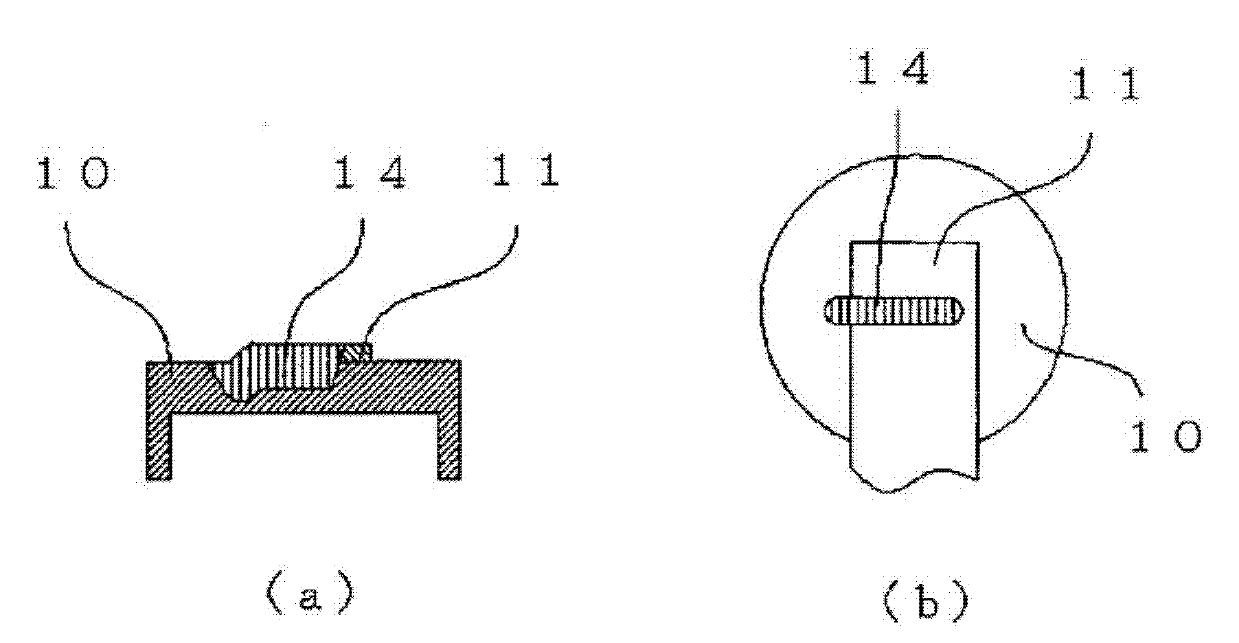
[0084] Using the electrode group 4 produced in the same manner as in Example 1, the width of the lead wire 11 is 2mm, and the welding part 14 is as Figure 4 As shown in (b), except that the surface of the lead wire 11 and the surface of the sealing plate 10 on the outside of both ends were laser welded in the same manner as in Example 1, a lithium ion secondary battery was produced, and the lithium ion secondary battery was fabricated. As Example 2.

Embodiment 3

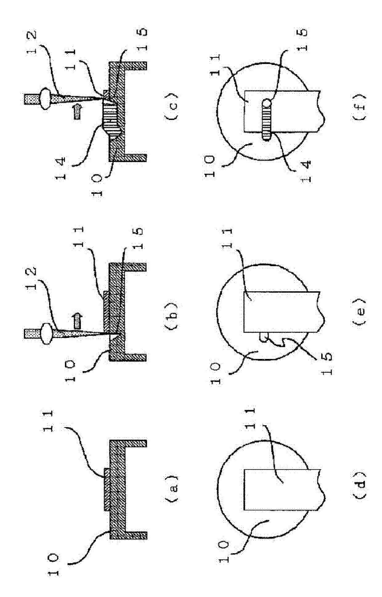
[0090] Using the electrode group 4 produced in the same manner as in Example 1, except that the fusion width of the welded portion 14 was set to 0.4 mm, and the fusion length was set to 1.6 mm, laser welding was performed in the same manner as in Example 1, thereby A lithium-ion secondary battery was produced.

[0091] As a result, a stable weld strength of about 15N was obtained. Therefore, it is preferable to set the ratio of the welding length to the welding width of the linear welding portion 14 to be 4 or more.

[0092] The joint strength is related to the welded area which is the product of the length of the welded part 14 and the welded width. If the weld width is made constant, it is related to the weld length. The welding width depends on the melting area when the laser beam 12 is irradiated, but the welding width is basically smaller because the smaller the melting area can suppress the generation of spatter. However, if the welding width is too small, it will be ...


PUM

PropertyMeasurementUnit
thicknessaaaaaaaaaa
widthaaaaaaaaaa
diameteraaaaaaaaaa

Abstract

Disclosed is a hermetically sealed battery comprising an electrode group (4) which is formed by coiling or laminating a positive electrode plate (1) and a negative electrode plate (2) with a separator (3) interposed therebetween and which is accommodated in a battery casing (5), the battery casing (5) including an opening which is sealed with a sealing plate (10). A lead (11) which leads out from either of the electrode plates in the electrode group (4) is laser-welded to the sealing plate (10), and a weld (14) between the lead (11) and the sealing plate (10) is formed as a line extending across at least the end of the lead (11).

Description

technical field [0001] The present invention relates to a sealed battery and its manufacturing method, and in particular to a joint structure of a lead drawn out from an electrode group and a sealing plate. Background technique [0002] In recent years, high-capacity aqueous electrolyte batteries represented by alkaline storage batteries and sealed type batteries such as non-aqueous electrolyte batteries represented by lithium-ion batteries have been widely used as power sources for driving portable electronic devices. Batteries are already widely used. Furthermore, with the multifunctionalization of electronic equipment and communication equipment in recent years, further increase in capacity of sealed batteries is desired. On the one hand, the high capacity of these sealed batteries has been developed, but on the other hand, safety measures should be taken seriously, especially due to internal short circuits in sealed batteries, there is a possibility that a rapid tempera...

Claims


Application Information

Patent Timeline
Patent Type & Authority Applications(China)
IPC IPC(8): H01M2/26H01M10/04H01M10/0587
CPCH01M10/0587H01M10/0431H01M10/0525Y02E60/122Y10T29/49108Y02E60/10Y02P70/50H01M50/528H01M50/531H01M50/172
Inventor 播磨幸男熊泽诚二船见浩司福冈孝博宫田恭介加藤诚一
Owner PANASONIC CORP
Why Eureka
Try Eureka