Electric steaming furnace with hot air flow

An electric steam oven and hot air technology, which is applied to steam cooking utensils, cooking utensils, household appliances, etc., and can solve problems such as potential safety hazards

Active Publication Date: 2011-10-05
广东天倬智能家居有限公司
View PDF7 Cites 11 Cited by
  • Summary
  • Abstract
  • Description
  • Claims
  • Application Information

AI Technical Summary

Problems solved by technology

Thus, when discharged by opening the door, there is a safety hazard

Method used


Image

  • Electric steaming furnace with hot air flow
  • Electric steaming furnace with hot air flow
  • Electric steaming furnace with hot air flow

Examples


Embodiment Construction

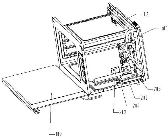
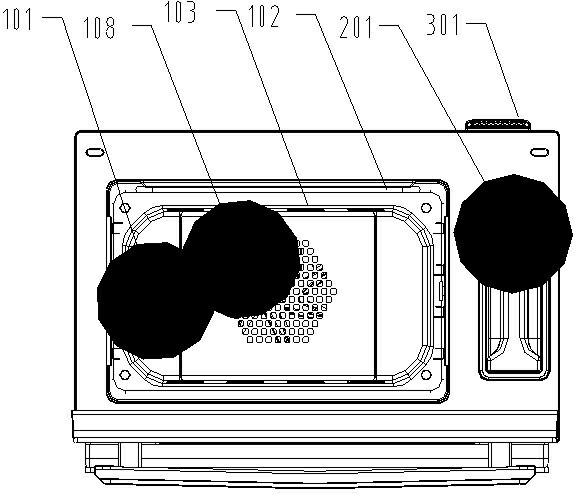
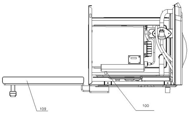
[0023] Such as figure 1 , figure 2 , image 3 , Figure 4 , Figure 5 and Figure 6 As shown, a hot air convection electric steam oven includes a furnace body 100, a furnace cavity 101, a heating wire 102, a convection plate 103, a centrifugal fan 104, a motor 105, a food bracket 106, food 107, an air inlet 108, and a furnace door 109. Hot air convection device 110, sealing ring 111, convection chamber 112, steam generating device 200, water storage device 201, water level sensing system 202, pumping system 203, heating pipe 204, steam inlet 205, constant pressure exhaust system 300, Exhaust outlet 301, residual water recovery port 302, air inlet 303, spring 304, connecting rod 305, compressible sealing ring 306, power push rod 307, front cover 308, rear cover 309, the furnace body 100 is provided with a furnace Cavity 101, the side of the furnace cavity 101 is provided with a steam generator 200 for providing steam to the furnace cavity 101, a kind of hot air convection...


PUM


Abstract

The invention relates to the technical field of kitchenware and discloses an electric steaming furnace with hot air flow. The electric steaming furnace comprises a furnace body, wherein the furnace body is provided with a furnace cavity, the side of the furnace cavity is provided with a steam generating device which provides steam for the furnace cavity, the furnace cavity is provided with an air intake used for absorbing steam, the air intake is correspondingly provided with an air draft device, the air intake is provided with a hot air flow device which is used for being communicated with the steam, the top of the furnace cavity is provided with a heating cavity, the heating cavity is provided with a heating coil used for heating the steam, the heating cavity is provided with an air outlet used for feeding heated overhigh-temperature steam into a cavity, and the furnace cavity is internally provided with a constant pressure exhaust system. The electric steaming furnace in the structure can cause the temperature of the furnace cavity to be uniform, the utilization rate of heat is high, the energy saving effect can be realized, and the electric steaming furnace has high safety.

Description

technical field [0001] The invention relates to the technical field of drinking utensils, in particular to the technical field of hot air convection electric steam oven. Background technique [0002] The Chinese utility model patent number is: 200720056489.X discloses a hot air convection steam heating device, which includes a cavity, a heating cavity surrounded by the cavity, a steam generator, a water tank for supplying water to the steam generator, and a A connector connecting the water tank and the steam generator, a steam nozzle for spraying the steam generated by the steam generator into the heating chamber, the water tank is placed on the outside of the heating chamber, and the feature is that the steam generator is installed on the other side of the heating chamber. On the outside, a heating pipe is arranged on the upper part of the heating chamber, and an air supply device is arranged on the outer side, upper part or rear part of the heating chamber. [0003] The f...

Claims


Application Information

Patent Timeline
Patent Type & Authority Applications(China)
IPC IPC(8): A47J27/04A47J36/00
Inventor 聂国顺傅平
Owner 广东天倬智能家居有限公司
Why Eureka
Try Eureka