Micro-lubrication equipment and method

A technology of lubricating equipment and lubricants, which is used in the direction of mechanical equipment, lubricating parts, engine lubrication, etc.

Inactive Publication Date: 2014-10-15
MWM微量润滑系统有限责任公司
View PDF10 Cites 0 Cited by
  • Summary
  • Abstract
  • Description
  • Claims
  • Application Information

AI Technical Summary

Problems solved by technology

[0011] The requirement to have a narrow monitoring area or vice versa is thus fulfilled, but monitoring of larger lubricant quantities over a larger area is not achievable with sensor monitoring optics

Method used


Image

  • Micro-lubrication equipment and method
  • Micro-lubrication equipment and method

Examples


Embodiment Construction

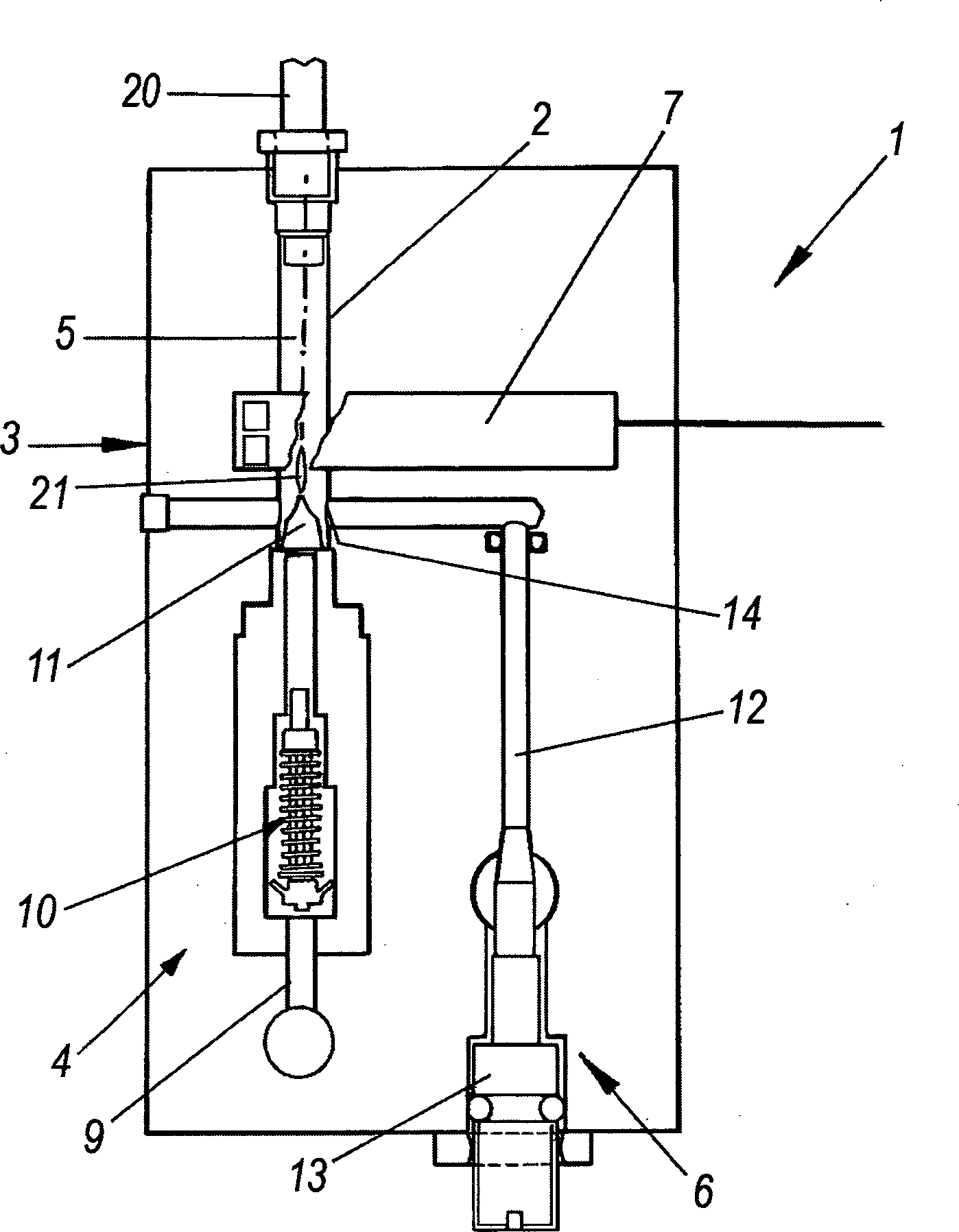
[0023] Referring to these figures, these figures show the use of two-phase mixture for the minimal lubrication equipment, the two-phase mixture through the mixing line 2 along the two-phase mixer 3 to distribute the first liquid lubricant phase 21 for the first The liquid lubricant phase is obtained in the flow of the second transport phase.

[0024] The mixing duct 2 is preferably made of a transparent material.

[0025] The first lubricant phase 21 is in particular oil and the second transport phase for the first phase is in particular air.

[0026] The use of the device 1 is in particular the micro-lubrication of ball bearings or the machining of chip removal tools.

[0027] The two-phase mixer 3 comprises: a first distribution unit 4 for metering the first phase distributed directionally along the axis 5 of the mixing duct 2; and a second supply unit 6 for feeding a flow of the second phase to the mixing in pipeline 2.

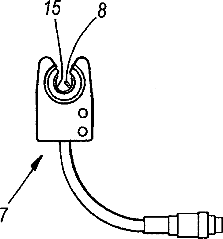
[0028] The sensor 7 for generating a signal indic...


PUM


Abstract

In the minimal lubrication process with a two-phase mixture flow obtained by dispensing a first liquid lubricant phase into a stream of a second pneumatic transport phase for the first phase along a mixing conduit of a two-phase mixer, the first phase is dispensed in a gauged manner by feeding it along an axis of the mixing conduit, a signal is generated indicating the presence of the two phases by a sensor positioned with its focal centre on the axis of the conduit within the mixer, and the lubrication control parameters are modified in relation to the variation of the presence signal.

Description

technical field [0001] According to the preamble of the main claim, the invention relates to a device and a method for minimal lubrication (in particular a device and method for minimal lubrication using an air-oil mixture, mainly for ball bearings or for lubricating chip removal machine tools). Such a device forms the subject of DE102006030651. Background technique [0002] Traditional minimal lubrication systems using lubricants in the form of an air-oil mixture are used for ball bearings of spindles in high-speed machine tools such as machining centers, milling machines, boring machines, grinding machines, punching machines, lathe centers and all bearings supporting high-speed rotating axes Minimal lubrication of rolling bearings. [0003] These lubrication systems often require prior verification of their operating conditions. In this respect, since they are used in industrial machinery that is often in continuous operation, they must be monitored for constant efficien...

Claims


Application Information

Patent Timeline
Patent Type & Authority Patents(China)
IPC IPC(8): B23Q11/12F16N29/00F16C33/66B23Q11/10
CPCB23Q11/122B23Q11/1046F16N7/32B23Q11/10B23Q11/123Y02P70/10
Inventor M·C·马佐尼
Owner MWM微量润滑系统有限责任公司
Why Eureka
Try Eureka