
Surface treatment method of cleaning air inlet

A technology of surface treatment and air inlet, which is applied in the field of surface treatment of clean air inlet, which can solve the problems of machining accuracy damage, fiber adhesion inside, and high labor intensity of a single piece, so as to achieve the effect of reducing requirements and meeting batch processing

Active Publication Date: 2013-04-10
苏州利达铸造有限公司
View PDF4 Cites 0 Cited by
  • Summary
  • Abstract
  • Description
  • Claims
  • Application Information

AI Technical Summary

Problems solved by technology

[0004] 1. The labor intensity of a single piece is high, requiring more manpower for batch processing;
[0005] 2. Manual grinding has high requirements for operators, and the relevant operators must undergo a long period of training to complete the relevant work;
[0006] 3. Purely manual grinding, there is uneven treatment, which will destroy the original machining accuracy;
[0007] 4. Pure manual grinding is difficult to avoid without leakage, which makes the cleaning of the air inlet in the subsequent use process will cause fibers to adhere to it, block the fiber outlet, and cause shutdown

Method used


Image

  • Surface treatment method of cleaning air inlet
  • Surface treatment method of cleaning air inlet
  • Surface treatment method of cleaning air inlet

Examples


Embodiment Construction

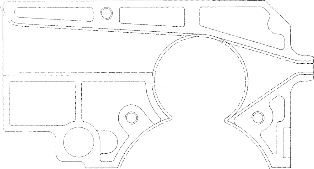
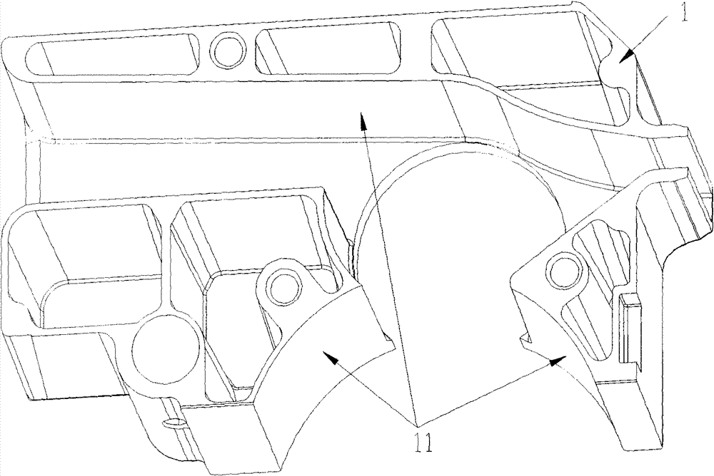
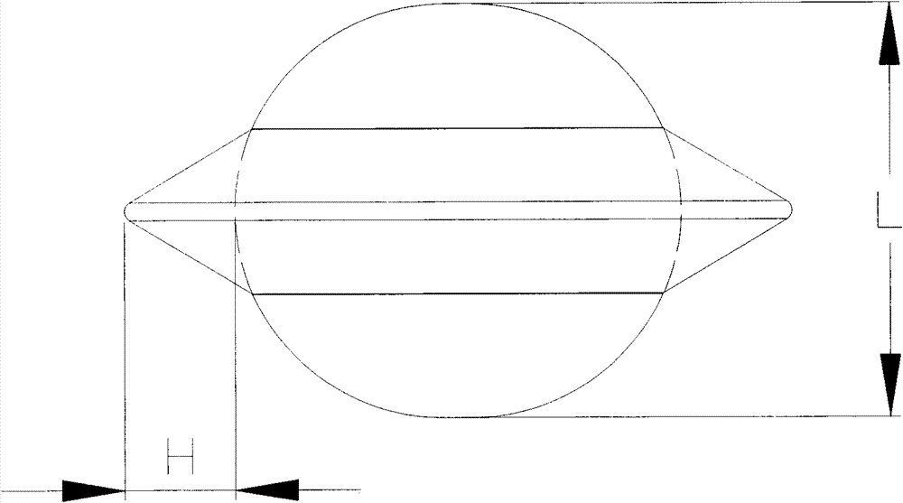
[0021] Put the clean air outlet 1 in the container of the vibrating finishing machine equipped with different grinding media, the vibration frequency is 35-40Hz, the vertical amplitude is 6.0-6.25mm, and the horizontal amplitude is 6.75-7.0mm. After different processing times, Test the surface roughness of the clean air outlet (including its internal channel 11 ), and the internal channel roughness. Different examples were obtained, see Table 1. There is no stainless steel flying saucer in the grinding media in Examples 1-3, and stainless steel flying saucers are included in the grinding media in other embodiments. see image 3 , 4 , the central portion of the flying saucer has a central ball 2 with an outer diameter L of 3-5 mm, and the periphery of the central ball 2 has an outwardly protruding annular band 3 with a substantially triangular cross-section, and the raised height H of the annular band is 20 of the outer diameter L of the central ball. -30%. See Table 1 for ...


PUM


Abstract

The invention provides a surface treatment method of a cleaning air inlet. The method has the advantages of uniformity in surface treatment and high efficiency, the surface roughness after treatment is within Ra0.6, and the surface roughness of an internal channel is within Ra0.4. The method comprises the steps of: placing a cleaning air inlet in a vibrating finishing machine, and grinding the surface of the cleaning air inlet by using a grinding medium, wherein the vibrating frequency of the finishing machine is 35-40Hz, the vertical amplitude is 6.0-6.25mm, and the horizontal amplitude is 6.75-7.0mm.

Description

technical field [0001] The invention relates to a surface treatment method for cleaning an air inlet. Background technique [0002] The clean air inlet is a key component of spinning. Its main function is to mechanically crush the cotton in the working chamber composed of the clean air inlet and the substrate to form a fine mixture of high-quality cotton yarn and impurities. Then, under the action of the air flow formed by the wind speed tube and the diversion block, the qualified high-quality cotton yarn and impurities are shunted out through the internal channel of the clean air inlet, and the high-quality cotton yarn is twisted into cotton thread through the follow-up mechanism. Therefore, the internal channel of this product has high requirements on surface quality, and there should be no burrs or rough areas caused by any process or operation, so as to avoid the cotton yarn sticking to block the channel and causing equipment shutdown. [0003] The original cleaning air...

Claims


Application Information

Patent Timeline
Patent Type & Authority Patents(China)
IPC IPC(8): B24B35/00
Inventor 季吉清
Owner 苏州利达铸造有限公司
Learn More