Wind power generation mechanism and electric motor car provided with same

A generator and transmission mechanism technology, applied in the field of electric vehicles, can solve the problems of insufficient power consumption, low utilization rate of wind energy, general energy storage effect, etc., and achieve the effect of improving driving mileage and range

Inactive Publication Date: 2011-10-12
林克祥
View PDF7 Cites 8 Cited by
  • Summary
  • Abstract
  • Description
  • Claims
  • Application Information

AI Technical Summary

Problems solved by technology

However, the wind power generator with this structure does not have a high utilization rate of wind energy when the electric vehicle is running or stationary, so its energy storage effect is very general. It is not enough to fully consume, and there is still the trouble of often charging at a fixed location

Method used


Image

  • Wind power generation mechanism and electric motor car provided with same
  • Wind power generation mechanism and electric motor car provided with same
  • Wind power generation mechanism and electric motor car provided with same

Examples


Embodiment 1

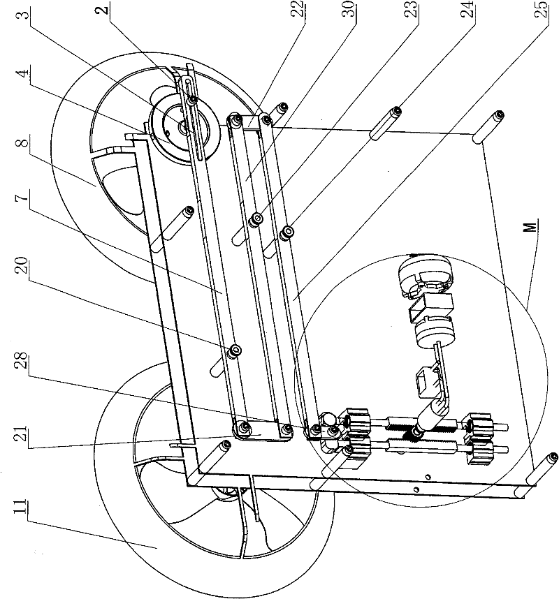
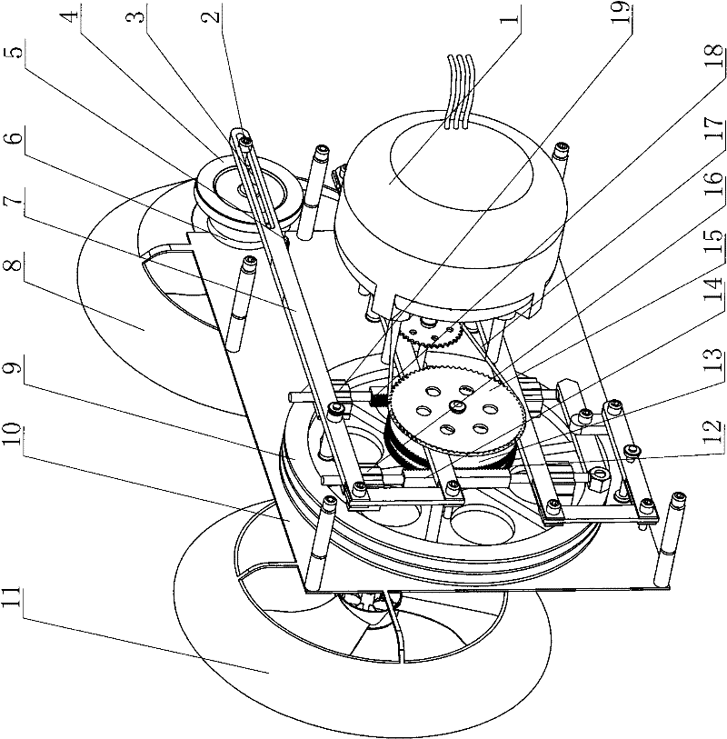
[0020] Embodiment one: refer to Figure 1 to Figure 5, this kind of wind power generation mechanism includes a main wind wheel 8, a rotating shaft 39 and a body 10, the main wind wheel 8 is mounted on the body 10 through the rotating shaft 39, and four swingable levers are installed on the body 10 7, 30, 25, 28, each lever is swingably mounted on the body 10 around the fulcrums 20, 23, 24, 34 respectively, and the head and tail of each lever are movably connected in turn; Connect, the two ends of connecting rod 21 are respectively hinged with the tail of the first lever 7 and the head of the second lever 30, through the connecting rod 22, the two ends of the connecting rod 22 are respectively connected with the tail of the second lever 30 and the third The head of the bar lever 25 is hinged, after the afterbody of wherein the third lever 25 is hinged with the connecting rod 29, the connecting rod 29 is hinged with the head of the fourth lever 28 again, and the afterbody of the...

Embodiment 2

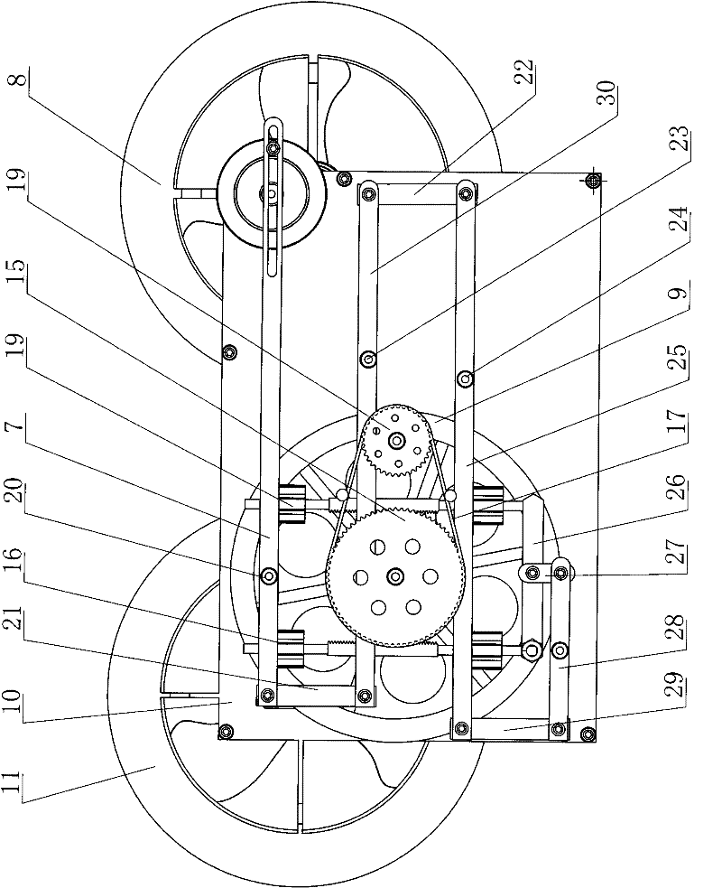
[0022] Embodiment two: refer to Figure 6 ~ Figure 7 , in the present embodiment, its lever is three, carries out head-to-tail movable connection respectively by connecting rod 21,22, and wherein connecting rod 28 is used as the push rod of air cylinder, but one end of the first lever 7 is hinged with connecting rod 56 and is connected with rotating disk 4 Eccentrically connected, its transmission mechanism includes a cylinder 57, a pneumatic motor 58, the push rod 28 of the cylinder 57 is connected to the tail end of the third lever 25, and the air outlet of the cylinder 57 is connected to the pneumatic motor 58 through the air pipe 60 , a one-way valve 59 is arranged on the air pipe 60. When the one-way valve 59 is closed, the purpose of gas storage is achieved; The transmission 55 is connected to the rotating shaft of the generator 1 . When the main wind wheel 8 and the auxiliary wind wheel 11 are subjected to the wind force, the turntable 4 is rotated by the transmission ...

Embodiment 3

[0023] Embodiment three: refer to Figure 8 ~ Figure 11 The difference between this embodiment and the first embodiment is that there is only one lever, and the transmission mechanism includes a first gear 43, a second gear 41, a first sprocket 44, a second sprocket 47, a first pinion 45, a first sprocket The second pinion 40 and the half-moon wheel 46, the first gear 43, the first sprocket 44 and the first pinion 45 are coaxially installed on the first rotating shaft 63, wherein the first sprocket 44 is integrated with the first pinion 45 set, and the first gear 43 and the second gear 41 are respectively installed on the first rotating shaft 63 and the second rotating shaft 64 through the one-way bearing, wherein the one-way bearing on the first gear 43 and the one-way bearing on the second gear 41 The bearing direction is opposite, the second gear 41 and the second sprocket 47 are coaxially installed on the second rotating shaft 64, the first sprocket 44 and the second sproc...


PUM


Abstract

The invention discloses a wind power generation mechanism which comprises a main wind wheel (8), a rotating shaft (39) and an engine body (10), wherein the main wind wheel (8) is installed on the engine body (10) through the rotating shaft (39). The wind power generation mechanism is characterized in that a swingable lever is installed on the engine body (10), one end of the lever is dynamically connected with the rotating shaft (39), and the other end of the lever is connected with a generator (1) through a transmission mechanism. According to the wind power generation mechanism with the structure, wind power is exponentially magnified by the lever through the transmission of the wind wheel, the generator is driven by a set of transmission mechanism to generate electricity, and the efficiency of wind energy is maximally utilized. The wind power generation mechanism provided by the invention has a simple structure, especially, when the wind power generation mechanism is installed on a transportation facility, continuous power generation can be realized, storage batteries of an automobile are in a state of efficient energy storage, and the distance and the range covered by the automobile are greatly increased.

Description

technical field [0001] The invention relates to a wind power generating mechanism and an electric vehicle equipped with the wind power generating mechanism. Background technique [0002] At present, electric vehicles have been widely valued as a non-polluting, low-energy transportation tool. The kinetic energy source of an electric vehicle is a rechargeable power storage device. The general power storage device has a relatively limited storage capacity. After a certain distance, an electric vehicle needs to be charged at a fixed location. Therefore, the driving mileage and driving range of an electric vehicle are greatly limited. . Although solar electric vehicles can use solar energy to supplement a certain amount of electric energy for the power storage device, they have the disadvantages of high cost, inability to work continuously and easy damage of solar panels in the case of cloudy and rainy days and other insufficient light, making it difficult to popularize and appl...

Claims


Application Information

Patent Timeline
Patent Type & Authority Applications(China)
IPC IPC(8): F03D9/00F03D1/02H02K7/18H02K7/116H02K7/10B60L8/00
CPCY02E10/72Y02T10/64Y02T10/7072
Inventor 林克祥
Owner 林克祥
Why Eureka
Try Eureka