Cabin dehumidificating and desalting micro positive pressure system of wind generating set at sea and in intertidal zone

A technology of micro-positive pressure for wind turbines, applied to wind turbine components, wind engines, wind power generation, etc., can solve problems such as low reliability, complicated operation, corrosion and short circuit, etc., to ensure service life and meet technical requirements High, cost-saving effect

Active Publication Date: 2011-10-12
SHANGHAI ELECTRIC WIND POWER GRP CO LTD +2
View PDF6 Cites 11 Cited by
  • Summary
  • Abstract
  • Description
  • Claims
  • Application Information

AI Technical Summary

Problems solved by technology

[0004] 1. The high humidity and high salt spray in the atmosphere have strong corrosion on the components of the unit. The longest anti-corrosion period of the anti-corrosion coating is 15 years, which cannot reach the design period of 20 years for wind turbines.
[0005] 2. Due to manufacturing process problems, some crevices are prone to occur. Once crevice corrosion occurs, the anti-corrosion layer will be helpless, and parts will soon be damaged due to corrosion or life will be shortened
[0006] 3. Although the anti-corrosion level has been improved, electronic components work in high salt spray and high humidity environments for a long time, salt spray particles will form on the surface, and a film will be formed on the surface of electronic components after moisture absorption, which may easily cause poor contact of electrical components , corrosion, short circuit and other hazards; mechanical parts are also prone to surface or contact surface corrosion, resulting in mechanical failure
[0007] 4. Increasing the anti-corrosion level or using the marine level for each component will result in a significan

Method used


Image

  • Cabin dehumidificating and desalting micro positive pressure system of wind generating set at sea and in intertidal zone
  • Cabin dehumidificating and desalting micro positive pressure system of wind generating set at sea and in intertidal zone

Examples


Embodiment Construction

[0016] The present invention will be further described below in conjunction with accompanying drawing.

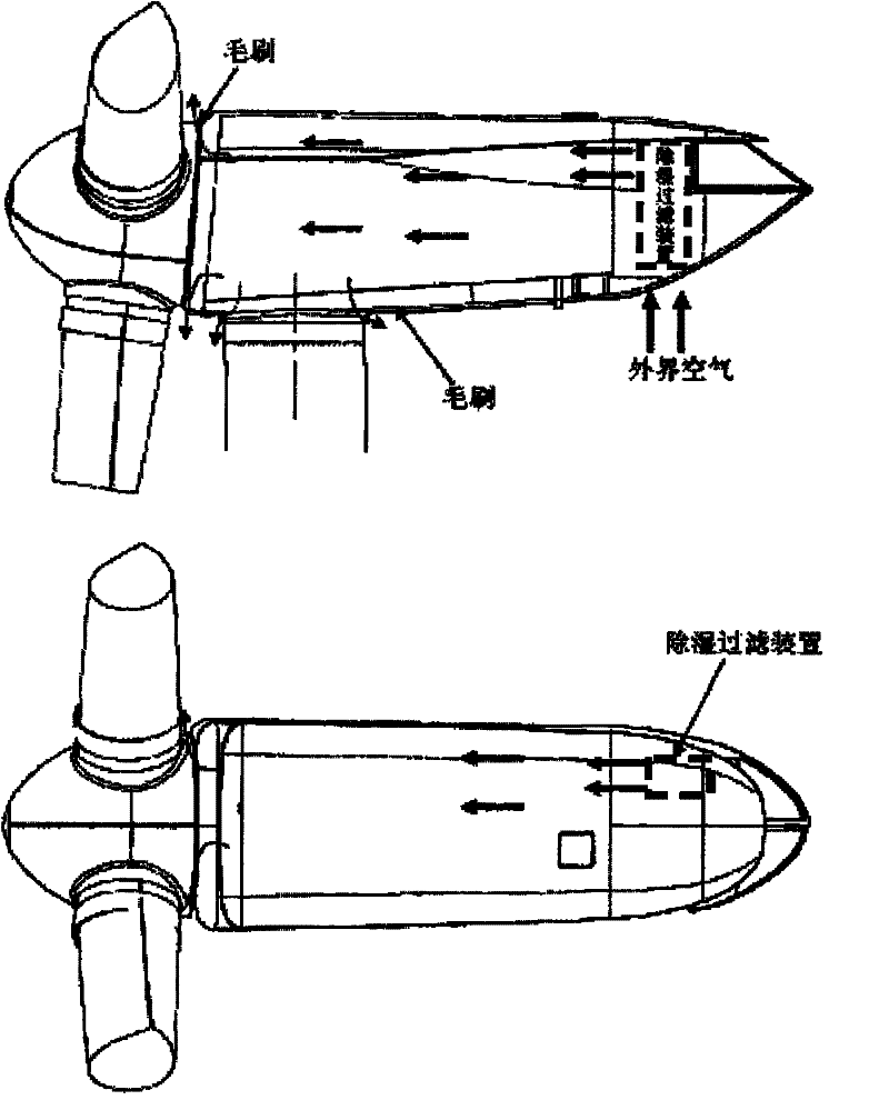
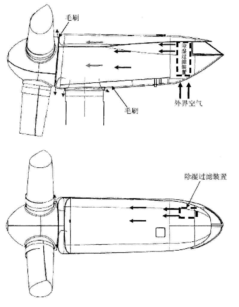
[0017] The diagram of the desalination and dehumidification air intake system in the engine room is shown in the attached figure;

[0018] The air intake system for desalination and dehumidification is located at the rear end of the engine room. Relatively independent air passages have been established for the generator and the gearbox cooler. A relatively airtight space is formed inside.

[0019] The desalination and dehumidification device set up at the air inlet ensures that the air entering the cabin is in an appropriate temperature range by condensing and dehumidifying the air and controlling the temperature of the air entering the cabin through the condensing device and the heating device, so as to ensure that the cabin will not High temperature or film of water condensed on the metal surface. At the same time, filter components are added to the desalination and deh...


PUM


Abstract

The invention relates to wind power generation equipment and discloses a cabin dehumidificating and desalting micro positive pressure system of a wind generating set at sea and in an intertidal zone. The system is characterized in that a dehumidification and filtration device is arranged on an appointed air inlet in a cabin; the other gap part except the appointed air inlet in the cabin is relatively sealed or is independent from an air passage way in the cabin, thus forming a relative sealed space; the air entering into the cabin from the appointed air inlet is subjected to dehumidification and filtration of particles with certain diameter; and through humidity, salt mist and flow control, the dehumidificated and desalted air which is relative dry and pure is filled into the whole cabin, thus forming a micro positive pressure, thereby ensuring the parts in the cabin to work in an environment similar to the land air environment and maximumly reducing the corrosion on the parts caused by the moist and salt fog at sea. In terms of the whole antiseptic system, only the local structure is improved, the system provided by the invention has the advantages of low cost, simplicity for implementation, high reliability, low technical requirement on the equipment and easiness for maintenance.

Description

Technical field: [0001] The invention relates to wind power plants. technical background: [0002] At present, wind power generation has developed rapidly in my country, and the installed capacity has shown explosive growth. With the massive development of onshore wind resources and the huge development prospects of offshore wind resources, it is natural to develop offshore wind power. Offshore wind resource conditions are better than those on land, and there are limited sites suitable for installing wind turbines on land. However, compared with onshore wind power generation, offshore wind power generation has many difficulties. Corrosion protection of offshore wind turbines is one of the difficulties. [0003] At present, the main methods used in China in terms of anti-corrosion are: improving the anti-corrosion level of parts; improving the insulation level or increasing the thickness of the anti-corrosion coating. These methods are relatively high in cost and low in rel...

Claims


Application Information

Patent Timeline
IPC IPC(8): F03D11/00
CPCY02E10/72
Inventor 陈晓静王凡
Owner SHANGHAI ELECTRIC WIND POWER GRP CO LTD
Why Eureka
Try Eureka