
In-situ dynamic sampling monitoring method and device for soil and underground water repair

A technology for groundwater remediation and dynamic sampling, which is applied in the direction of measuring devices, sampling devices, instruments, etc., can solve the problems of high cost, time-consuming, and inability to control and provide, and achieve the effect of low cost, convenient operation, and accurate positioning

Inactive Publication Date: 2011-10-12
CHONGQING UNIV
View PDF2 Cites 18 Cited by
  • Summary
  • Abstract
  • Description
  • Claims
  • Application Information

AI Technical Summary

Problems solved by technology

[0005] The currently used soil sampling method is designed to meet the needs of site quality assessment. It is a one-time sampling and does not require repeated monitoring at the same monitoring point at regular intervals. It is only applicable to the evaluation stage before restoration and the acceptance stage after restoration. In the restoration process, the existing method requires repeated digging and backfilling; then digging and backfilling; this repetition seriously disrupts the concentration distribution of pollutants in the monitoring hole in the vertical direction technically, so that the two times before and after The monitoring results cannot be compared point by point in the depth direction, and cannot provide necessary and accurate information for the regulation and control of the repair process; economically, due to repeated excavation and backfilling, the cost is high and time-consuming

Method used


Image

  • In-situ dynamic sampling monitoring method and device for soil and underground water repair
  • In-situ dynamic sampling monitoring method and device for soil and underground water repair
  • In-situ dynamic sampling monitoring method and device for soil and underground water repair

Examples


Embodiment Construction

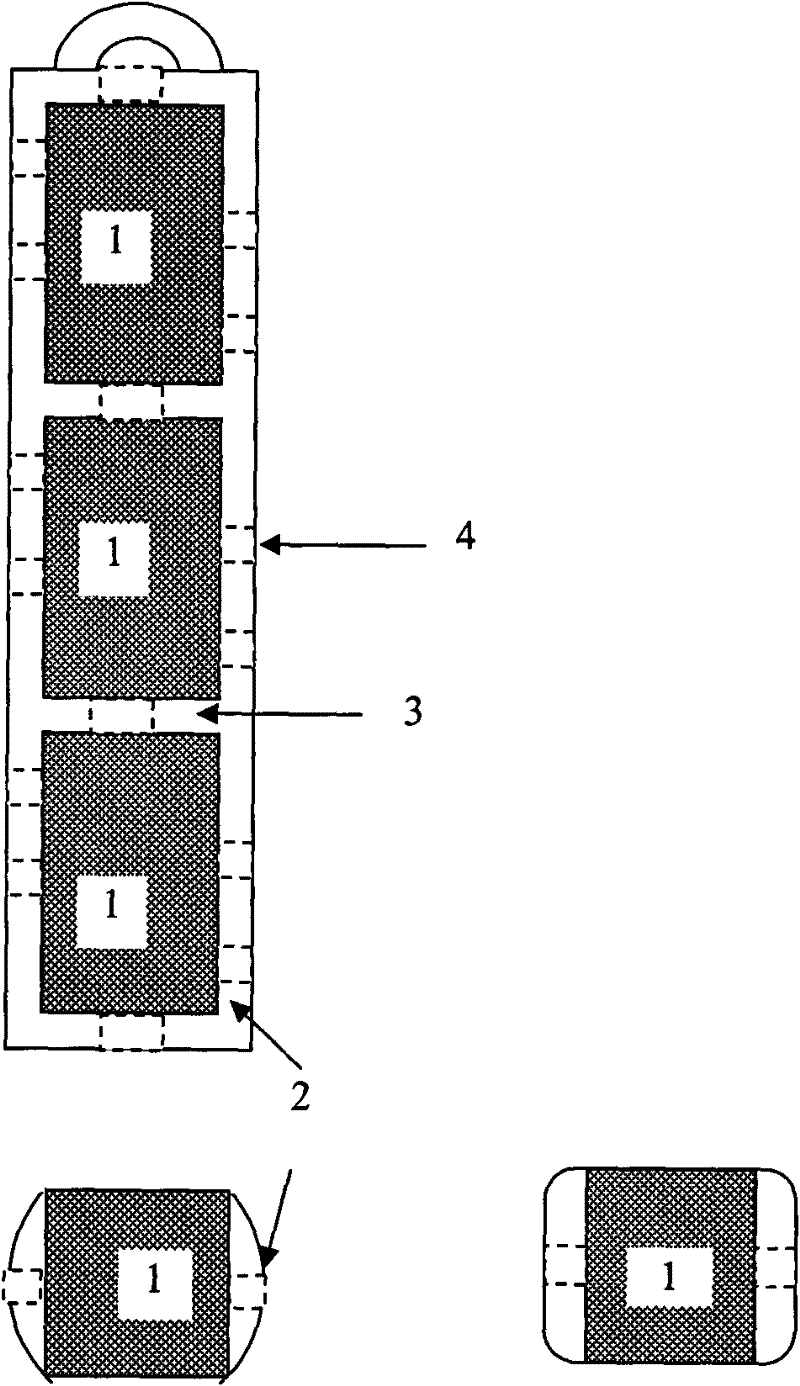
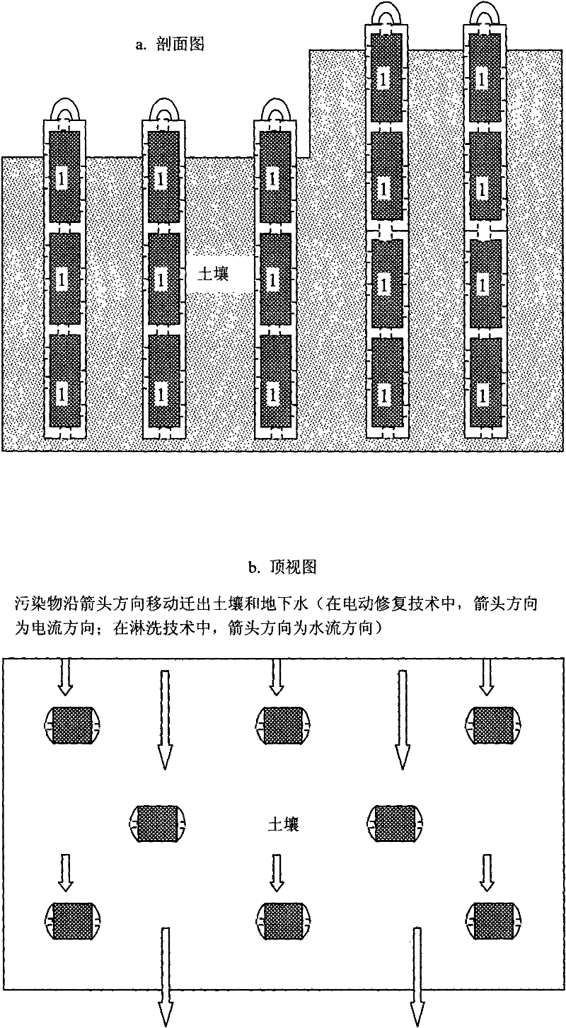
[0016] (1) According to the requirements of the restoration plan, use manual excavation or mechanical drilling to excavate sampling holes in the restoration site, and the diameter of the sampling holes should be slightly larger than figure 1 and figure 2 The outer diameter of the in-situ dynamic sampling device shown, the depth of the sampling hole is determined by the repair scheme. The soil excavated when digging holes should be placed in order of depth for use in (3);

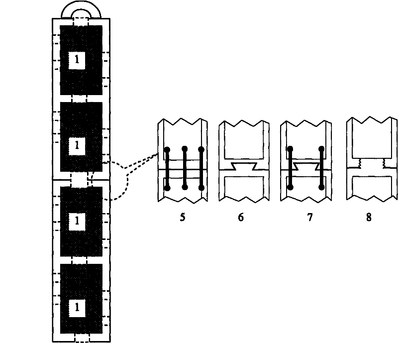
[0017] (2) According to the depth of the sampling hole, select in-situ dynamic sampling devices of different lengths. For deeper sampling holes, use figure 2 The module splicing form shown increases the length of the sampling device;

[0018] (3) Fill the soil dug out in the step (1) into the cavity in the middle of the sampling device according to the original upper and lower order, and compact and smooth;

[0019] (4) Mark the depth position of each monitoring point in the monitoring hole on the devic...


PUM

PropertyMeasurementUnit
Diameteraaaaaaaaaa

Abstract

The invention relates to a soil in-situ dynamic sampling monitoring method and a soil in-situ dynamic sampling monitoring device for estimating repair results dynamically in the process of repairing soil and underground water. The method comprises the following steps of: excavating a monitoring hole in a mode of artificial excavation or equipment drilling, filling soil generated in the process of excavating into an in-situ dynamic sampling device according to the original sequence, marking the depth position of each monitoring point, and arranging the device in the monitoring hole; when monitoring is required in the repair process, drawing the sampling device out of the monitoring hole, and aligning a nondestructive testing instrument with each monitoring point in the sampling device by using a lossless detection instrument to perform detection; and after the detection is finished, inserting the sampling device into the monitoring hole again. Next sampling can be accomplished by repeating the same operating steps. In the sampling device, a rectangular run-through hole is formed in the middle of a hard plastic rod with a cylindrical or rectangular cross section to be used for storing the soil, and rib plates with holes are arranged in the middle of the sampling device to enhance the strength of the device. The sampling device is manufactured in a modular mode, and is jointed to different lengths according to the depth of the monitoring hole.

Description

technical field [0001] The invention relates to a sampling monitoring method required for dynamic monitoring and evaluation of the restoration effect during the restoration of polluted soil and groundwater. Background technique [0002] When the waste water and solid waste generated in the process of industrial production enter the soil, it will cause pollution of the soil and groundwater. When the site is changed to residential, agricultural and other land, the soil and groundwater must be restored to eliminate the pollutants. [0003] The main methods of soil and groundwater remediation are: (1) Physical remediation: physical separation remediation, curing / stabilization remediation, steam extraction remediation, electric remediation, etc.; (2) Chemical remediation: chemical leaching remediation, solvent extraction remediation, High temperature incineration repair, redox repair, etc.; (3) Bioremediation: prepared bed method, soil heap decay method, mud bioreactor method, la...

Claims


Application Information

Patent Timeline
IPC IPC(8): G01N23/223G01N1/04
Inventor 李东
Owner CHONGQING UNIV
Learn More