Stator and rotor structure of permanent magnet motor
A permanent magnet motor, rotor structure technology, applied in the shape/style/structure of the magnetic circuit, the rotating parts of the magnetic circuit, the static parts of the magnetic circuit, etc. Large torque ripple, affecting the efficiency of permanent magnet motors, etc., to achieve the effect of reducing torque ripple, improving efficiency, and reducing heat generation
- Summary
- Abstract
- Description
- Claims
- Application Information
AI Technical Summary
Problems solved by technology
Method used
Image

Examples
Embodiment Construction
[0022] In order to better understand the technical solution of the present invention, a detailed description will be given below through specific embodiments and in conjunction with the accompanying drawings.
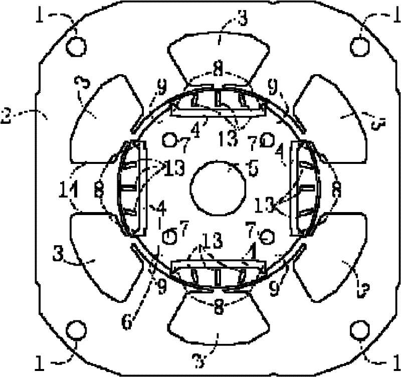
[0023] see figure 1 , a stator and rotor structure of a permanent magnet motor of the present invention, comprising stator and rotor cores 2, 6, wherein,
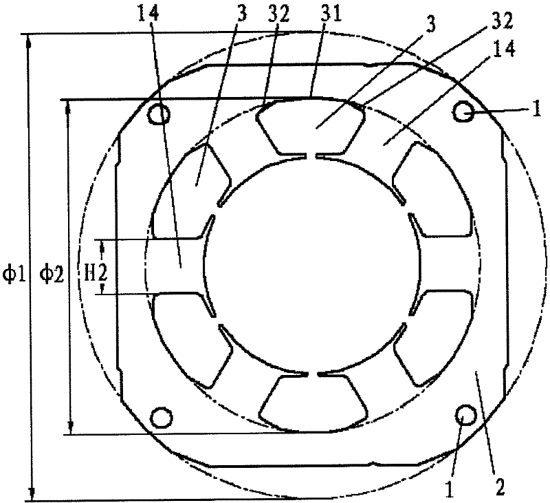
[0024] on stator core 2 (see figure 2 ) is provided with a plurality of stator slots 3 located on the inner circle of the stator core 2 and stator teeth 14 between two adjacent stator slots 3; the stator teeth 14 are T-shaped, so that the distribution of magnetic force lines is smooth and even;
[0025] The slot bottom of the stator slot 3 is formed by a circular arc 31 and a straight line 32 connected to both ends of the circular arc 31;
[0026] The ratio of the diameter φ2 of the arc 31 of the stator slot 3 to the outer longitude φ1 of the stator core 2, that is, the optimal setting of φ2 / φ1 is 0.7 to 0.74;
...
PUM
 Abstract
Description
Claims
Application Information
 - Generate Ideas
- Intellectual Property
- Life Sciences
- Materials
- Tech Scout
- Unparalleled Data Quality
- Higher Quality Content
- 60% Fewer Hallucinations
Browse by: Latest US Patents, China's latest patents, Technical Efficacy Thesaurus, Application Domain, Technology Topic, Popular Technical Reports.
© 2025 PatSnap. All rights reserved.Legal|Privacy policy|Modern Slavery Act Transparency Statement|Sitemap|About US| Contact US: help@patsnap.com