Glow plug with metallic heater probe

一种热探针、电热塞的技术,应用在电路、电阻器、电气元件等方向,能够解决电热塞成本增加等问题,达到避免高应力的效果

Inactive Publication Date: 2011-10-12
FEDERAL MOGUL IGNITION
View PDF4 Cites 2 Cited by
  • Summary
  • Abstract
  • Description
  • Claims
  • Application Information

AI Technical Summary

Problems solved by technology

However, since ceramic probes are more expensive than metal probes, the cost of glow plugs increases

Method used


Image

  • Glow plug with metallic heater probe
  • Glow plug with metallic heater probe
  • Glow plug with metallic heater probe

Examples


Embodiment Construction

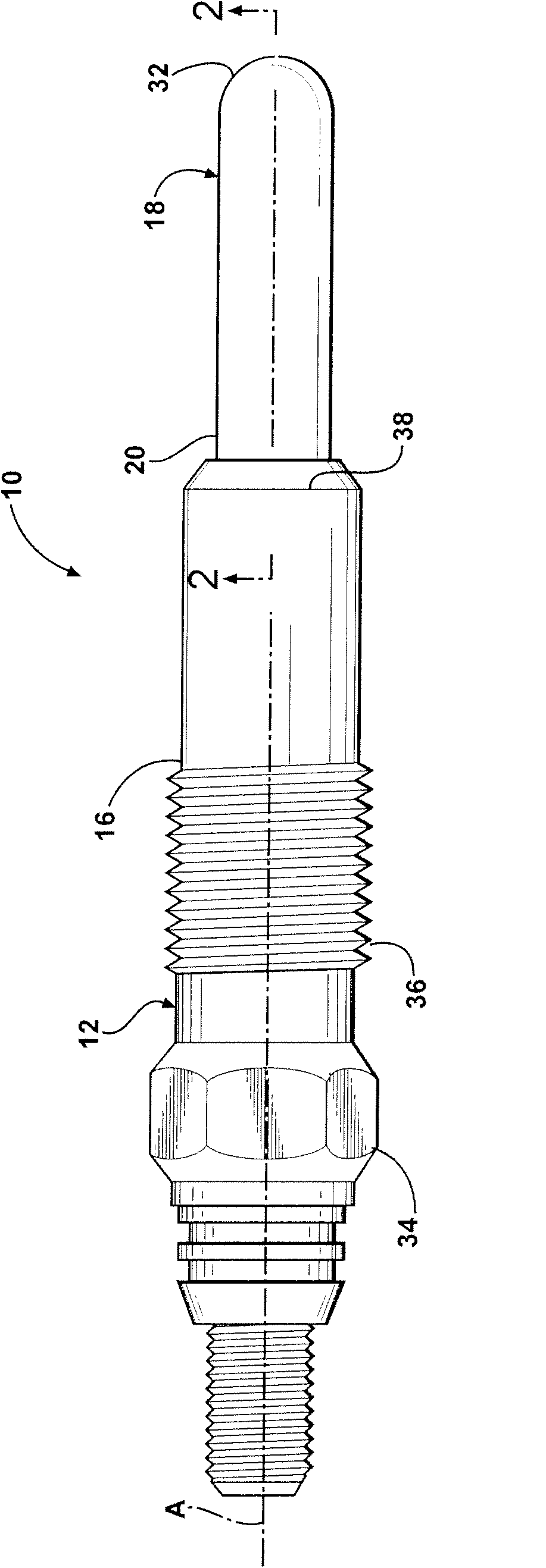
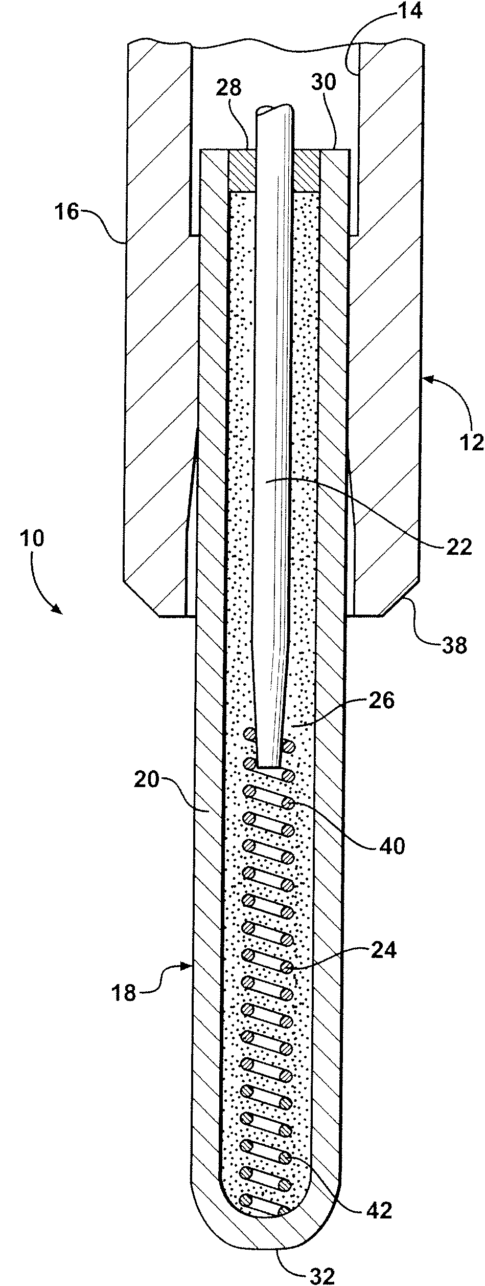
[0018] Referring to the drawings, wherein like numerals indicate like or corresponding parts in the various figures, a glow plug according to the prior art is shown generally at 10 in FIGS. 1 and 2 . The glow plug 10 comprises an annular metal casing 12 having a bore 14 extending along an imaginary longitudinal axis A. As shown in FIG. Housing 12 may be made of any suitable metal, such as various steels. Housing 12 may also include a plating or coating, such as nickel or a nickel alloy, on some or all of its surfaces, including outer surface 16 and the interior of bore 14, to enhance its resistance to high temperature oxidation and corrosion.

[0019] The glow plug assembly 10 includes a heat probe, indicated generally at 18 . Thermal probe 18 includes metal sheath 20 , electrode 22 , resistive heating element 24 , powder fill material 26 and seal ring 28 . The sheath 20 is an electrically and thermally conductive member of generally tubular construction. Any suitable metal...


PUM


Abstract

A glow plug assembly (110) has a metallic heater probe (118) supported within a metal shell (112). A transition zone (144) at the base of the shell (112) includes a membrane (146) and a tube portion (148). A first open end (130) of the heater probe (118) is formed with a reduced diameter pilot section (150) that mates with the tube portion (148) to establish a joint area between the components. The membrane (146) may be made elastically deflectable so as to accommodate integration of a pressure sensor (156) in the glow plug assembly (110).

Description

[0001] Cross References to Related Applications [0002] none. technical field [0003] This invention relates to glow plugs for assisting cold-start combustion in combustion chambers, and more particularly, to a glow plug with a metallic thermal probe. Background technique [0004] Glow plugs are typically used in direct start or assisted start applications that require a high heat source for combustion. As a result, glow plugs are used in small heaters, industrial electric stoves, and diesel engines, among others. Glow plugs for diesel engines are generally classified as open coil or sheathed devices. Sheath type glow plugs are divided into ceramic thermal probe type and metal thermal probe type. In metal-sheathed thermal probes, one or more helically wound resistance wires are housed in a metal sheath, embedded in an electrically insulating and thermally conductive powder. For example, US Patent 4,963,717 describes a glow plug of this type. The resistance wire locat...

Claims


Application Information

Patent Timeline
Patent Type & Authority Applications(China)
IPC IPC(8): F02P19/02F23Q7/00H01C1/03
CPCF02P19/02F23Q7/001F23Q7/22H01C1/03
Inventor 约翰·A·伯罗斯马塞洛·西诺桑德罗·戈雷蒂
Owner FEDERAL MOGUL IGNITION
Why Eureka
Try Eureka