Method and device for transferring heat

A device and component technology, applied in the field of energy transmission, which can solve the problems of wear and tear of movable parts of mechanical heat pumps, harmful environmental effects, and low coefficient of performance

Inactive Publication Date: 2011-10-12
雅尼·奥克萨南 +1
View PDF1 Cites 2 Cited by
  • Summary
  • Abstract
  • Description
  • Claims
  • Application Information

AI Technical Summary

Problems solved by technology

Weaknesses of these solutions are large size, harmful impact on the environment and wear of the moving parts of the mechanical heat pump and in the case of thermoelectric heat pumps low coefficient of performance

Method used


Image

  • Method and device for transferring heat
  • Method and device for transferring heat
  • Method and device for transferring heat

Examples


Embodiment Construction

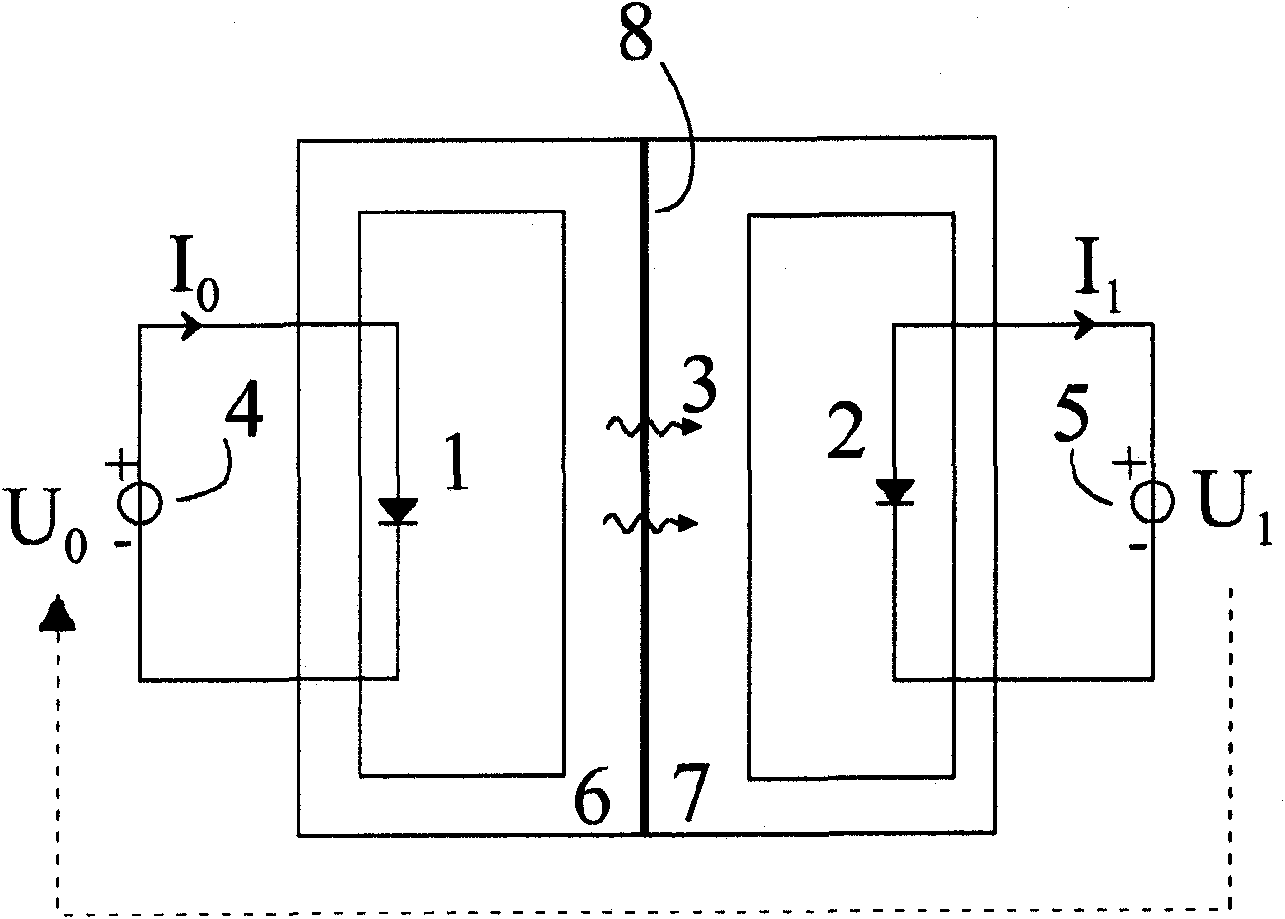
[0012] An example of the operation principle and structure of the heat pump operated by light according to the embodiment of the present invention is described below. It will be noted that instead of light, the heat pump may transfer heat by means of other electromagnetic radiation.

[0013] exist figure 1 , the radiation-emitting element 1 emits radiation 3 by means of an external energy source 4 . The element 1 may for example comprise a light-emitting diode emitting light by electroluminescence, while the external energy source 4 may be a figure 1 The circuit provides the current I for the light-emitting diode 0 The voltage source U 0 . The emitted radiation 3 is delivered to the radiation-absorbing element 2, wherein part of the energy comprised in the radiation is released as heat and part of the energy is recovered in an external element 5 in a readily available form of energy, such as electrical or mechanical energy. Element 2 may be, for example, a light emitting ...


PUM


Abstract

A method and device for transferring heat in a heat pump, where heat energy is transferred with the aid of light or other electromagnetic radiation from an element emitting radiation to an element absorbing radiation in a direction opposite to the direction defined by the second law of thermodynamics and in which a part of the energy of the absorbed radiation is converted back to an exploitable form of energy, like electrical or mechanical energy.

Description

technical field [0001] The present invention relates primarily to energy transfer. The invention particularly relates to the transfer of thermal energy by means of electromagnetic radiation, such as light. Background technique [0002] Known heat transfer methods routinely use various refrigerants (eg, compressor-based solutions in refrigerators) or electric current (Peltier elements). The disadvantages of these solutions are the large size, the harmful impact on the environment and the wear of the movable parts of the mechanical heat pump and, in the case of thermoelectric heat pumps, the low coefficient of performance. Contents of the invention [0003] According to a first aspect of the invention there is provided a method as claimed in claim 1 . [0004] In some embodiments of the present invention, heat transfer may occur in a direction opposite to that determined by the second law of thermodynamics. [0005] In some embodiments of the invention, light or other ele...

Claims


Application Information

Patent Timeline
Patent Type & Authority Applications(China)
IPC IPC(8): F25B23/00H01L33/00
CPCF25B21/00H01L31/167H02S10/30Y02B30/00Y02E10/50F25B23/003G05D23/1919H01L33/00
Inventor 雅尼·奥克萨南雅科·蒂尔基
Owner 雅尼·奥克萨南
Why Eureka
Try Eureka