Charging station

A charging station and charging machine technology, applied in the field of charging stations, can solve the problems of large volume, low charging efficiency, poor overload capacity, etc., and achieve the effects of man-machine exchange, good constant current effect, and high charging efficiency

Inactive Publication Date: 2011-10-19
ZHUHAI YINLONG ELECTRICAL APPLIANCES +1
View PDF2 Cites 9 Cited by
  • Summary
  • Abstract
  • Description
  • Claims
  • Application Information

AI Technical Summary

Problems solved by technology

For chargers equipped with power frequency transformers, they are bulky, bulky, use a large amount of copper, have high cost and low charging efficiency; and for chargers equipped with high frequency transformers, because of the small size of the high frequency inverter, The light-weight high-frequency magnetic core material greatly improves the power density of the circuit, making the no-load loss of the inverter power supply very small, and the inverter efficiency is improved. Usually, the peak conversion efficiency of high-frequency inverters reaches more than 90%, but It also has significant disadvantages: the high-frequency inverter cannot be connected to a full-load inductive load, and its overload capacity is poor. With the current technology, it is impossible to make a single power very large. To make a high-power charger, multiple sets must be connected in parallel. The use increases the complexity and cost of the equipment, the average failure rate of the equipment is high, and the reliability is poor

Method used


Image

  • Charging station
  • Charging station
  • Charging station

Examples


Embodiment Construction

[0037] The solution of the present invention will be described in detail below in conjunction with the accompanying drawings and preferred embodiments.

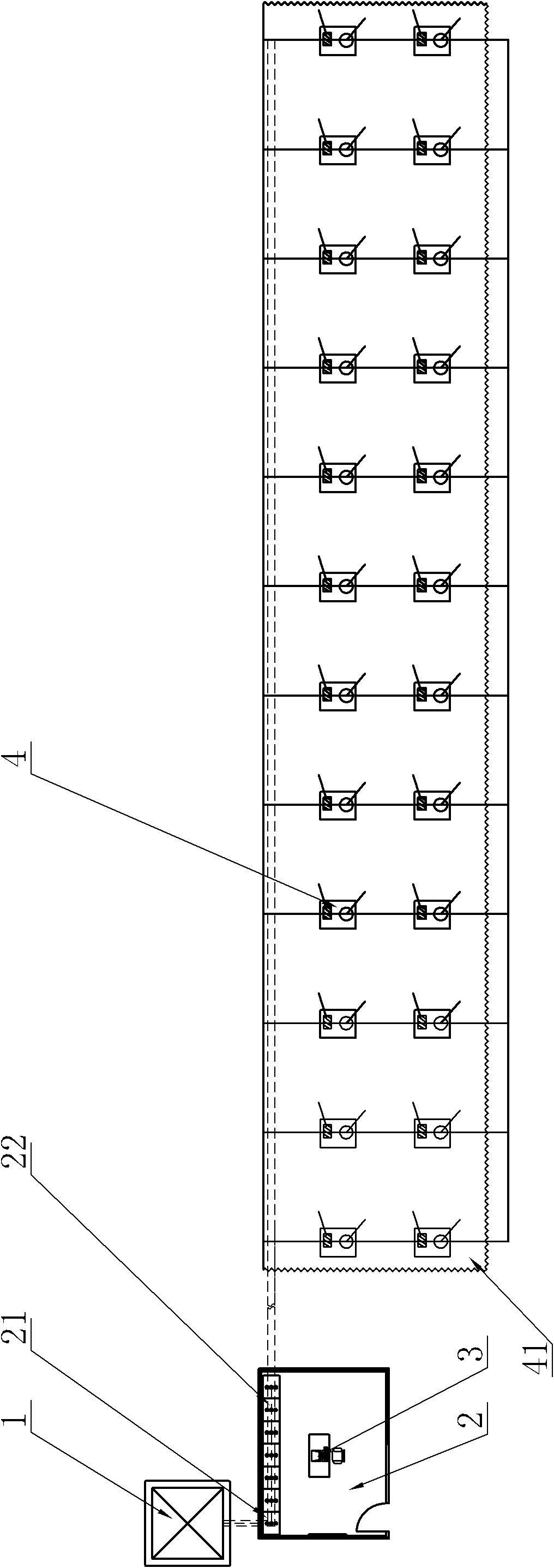
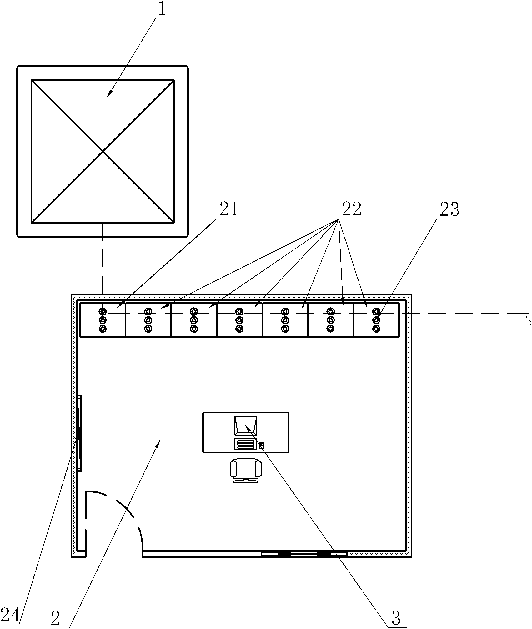
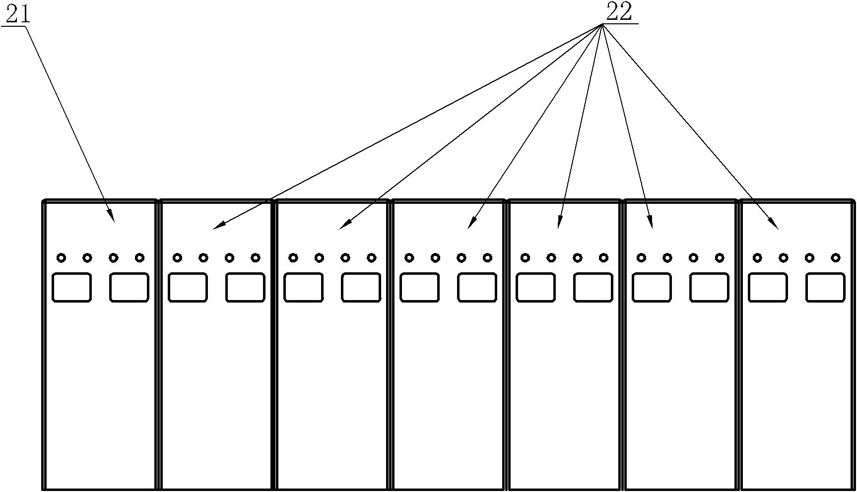
[0038] Such as figure 1 , figure 2 , image 3 , Figure 4 As shown, the present invention includes a power transformer 1, a charging machine room 2 and a charging pile 4. The charging machine room 2 is provided with a clustered electric cabinet and a central control computer 3. The clustered electric cabinet consists of a main control switch cabinet 21 and several standard charging A cabinet 22 is formed; a plurality of charging piles 4 are dispersedly arranged in a way that facilitates parking and charging of electric vehicles, and a rainproof shed 41 is arranged on the top of the charging piles 4 .

[0039]The input end of the power transformer 1 is connected to the high-voltage power grid, and its neutral point is not grounded; the output end of the power transformer 1 is connected to the input end of the main control ...


PUM


Abstract

The invention discloses a charging station with the advantages of low cost, high reliability and high charging efficiency. The charging station comprises a power transformer and a charging machine room, wherein a cluster electric cabinet is arranged inside the charging machine room and consists of a master control switch cabinet and a plurality of standard charging cabinets; at least one group of charging modules are arranged in each standard charging cabinet; each charging module comprises a current-limiting module (221), a rectifier bridge (222) and a charging socket (223); the current-limiting module (221) consists of a plurality of capacitors (C) and controls an output state of each capacitor (C) through a contactor; and alternating current entering through an input end of the charging module passes through the current-limiting module (221) and the rectifier bridge (222) and is changed into direct current and is output through the charging socket (223). The charging station is used for charging a power storage battery on an electric automobile.

Description

technical field [0001] The invention relates to a charging station for charging a power storage battery on an electric vehicle. Background technique [0002] At present, people's awareness of environmental protection is increasing, and they pay more and more attention to the protection of the environment and the effective and rational use of energy. The fuel consumption and exhaust emissions of traditional vehicles far exceed people's expected values. Therefore, electric vehicles, which are clean energy sources, will emerge at the right time, and will quickly replace and replace fuel vehicles with their advantages in energy saving and environmental protection. [0003] The power source of electric vehicles is the vehicle-mounted traction battery. Timely and fast replenishment of power to the traction battery is an urgent problem to be solved in the process of promoting the promotion and mass production of electric vehicles at this stage. To supplement electric energy for th...

Claims


Application Information

Patent Timeline
Patent Type & Authority Applications(China)
IPC IPC(8): H02J7/00H02J7/02
Inventor 覃美莲
Owner ZHUHAI YINLONG ELECTRICAL APPLIANCES
Why Eureka
Try Eureka