Hybrid excitation E-shaped iron core axial magnetic field permanent magnet brushless motor

A technology of permanent magnet brushless motor and axial magnetic field, which is applied to the direction of motor, magnetic circuit shape/style/structure, electromechanical device, etc. Effect of small size and improved reliability

Inactive Publication Date: 2011-10-19
SOUTHEAST UNIV
4 Cites 46 Cited by

AI-Extracted Technical Summary

Problems solved by technology

[0005] Technical problem: Aiming at the difficulty of adjusting the magnetic field of the axial magnetic flux switching stator permanent magnet motor, the power density of the motor can be increased without increasing the volume ...

Method used

When motor was in position shown in Fig. 3, Fig. 4, rotor tooth P was opposite to a stator tooth that was wound around concentrated armature coil, and according to the magnetization direction of permanent magnet, permanent magnet flux passed through from the tooth of stator 1 The air gap 10 penetrates into the teeth of the rotor P and then passes through the air gap 11 into the teeth of the stator 2, and the value is the largest. At this time, if the electric excitation magnetic potential in the same direction as the permanent magnet magnetic potential is applied through the excitation winding, the magnetic flux in the armature winding of the turn chain can be increased, and the induced electric potential can be increased (as shown in Figure 3). On the contrary, if the direction of the excitation current is changed so that the direction o...

Abstract

The invention discloses a hybrid excitation E-shaped iron core axial magnetic field permanent magnet brushless motor, which comprises two stators, permanent magnets (4), three-phase concentrated armature windings (6), single-phase concentrated excitation windings (7) and a rotor (2). A fan-shaped permanent magnet is arranged between every two E-shaped stator iron cores; the three-phase concentrated armature windings are wound on the teeth of the two stators; and the excitation windings are wound on the middle teeth of the E-shaped stator iron cores. By the excitation windings and the armature windings, the capability of adjusting and controlling an air gap magnetic field of the motor is improved; the speed adjustment range of the motor is effectively broadened; the motor is ensured to have higher torque output capability and higher power density; by two sets of excitation sources provided by the permanent magnets and the excitation windings, the operation reliability of a system is greatly improved, and the fault-tolerant operation of the motor is realized; by a simple rotor structure, the operation reliability and the dynamic performance of the motor are improved; and because the motor has a smaller axial size, the motor is very suitable for places requiring thin installation strictly, such as a hub driving motor for an electric vehicle and the like.

Application Domain

Technology Topic

Image

  • Hybrid excitation E-shaped iron core axial magnetic field permanent magnet brushless motor
  • Hybrid excitation E-shaped iron core axial magnetic field permanent magnet brushless motor
  • Hybrid excitation E-shaped iron core axial magnetic field permanent magnet brushless motor

Examples

  • Experimental program(1)

Example Embodiment

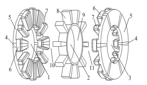
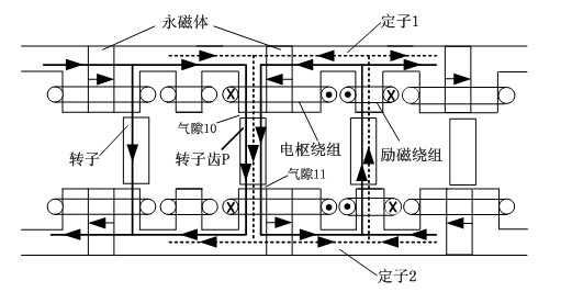
[0021] The hybrid excitation E-shaped iron core axial magnetic field permanent magnet brushless motor of the present invention includes a first stator, a rotor, a second stator, a permanent magnet, a three-phase concentrated armature winding and a single-phase concentrated excitation winding;
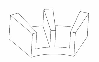
[0022] The first stator and the second stator are located on both sides of the rotor. Each stator has 6 E-shaped iron cores and 6 armature coils. Every two armature coils are connected in series to form a three-phase armature winding. The three-phase armature windings on the two stators are connected in series to form the three-phase concentrated armature windings of the A-phase, B-phase, and C-phase of the whole motor; each stator has 6 excitation coils, all of which are Concentrated winding, wound on the teeth in the middle of the stator E-shaped iron core, the above 6 coils are connected in series end to end in sequence to form a single-phase concentrated excitation winding;
[0023] A permanent magnet is arranged between every two E-shaped iron cores, and the three-phase concentrated armature winding is wound on the two E-shaped iron core teeth; the excitation directions of the symmetrical permanent magnets on the first stator and the second stator are opposite; The permanent magnets on the first stator and the second stator are alternately magnetized along the circumferential direction, and the magnetization directions of adjacent permanent magnets are opposite.
[0024] There are 10 teeth on the rotor, which are called 10 rotor poles. The rotor poles are all fan-shaped, and their shape is consistent with the tooth shape of the stator E-shaped iron core. The rotor poles are evenly arranged on the outer circumference of the rotor non-magnetic ring. The axial thickness of the rotor pole is equal to the axial thickness of the non-magnetically conductive ring, and there is neither permanent magnet nor winding on the rotor.
[0025] The teeth and slots of the E-shaped stator core are sector-shaped, consistent with the sector-shaped rotor poles, and both the armature winding and the field winding are concentrated windings.
[0026] The stator of the "Basic Motor" is composed of 3 E-shaped iron core units and 3 permanent magnet units. The rotor is composed of 5 rotor poles and a non-magnetically conductive ring. The rotor poles are embedded on the non-magnetically conductive ring. The stator unit/rotor pole of the basic motor is expanded by integer multiples, and the motor with structure of 6/10, 12/20, 18/30, etc. can be obtained.
[0027] details as follows:
[0028] The hybrid excitation E-shaped iron core permanent magnet brushless motor proposed in the present invention includes: two stators, sector-shaped permanent magnets, three-phase concentrated armature windings, single-phase concentrated excitation windings and a rotor; the rotor is sandwiched between the two stators, The stator and the rotor are installed coaxially with an air gap between them. The stator structures on both sides of the rotor are exactly the same, and the positions are symmetrical about the rotor; the E-shaped iron core and permanent magnets of the stator are alternately placed to form a disc shape. The magnetization directions of two adjacent permanent magnets on the same stator are opposite. The excitation directions of the two opposite permanent magnets are opposite; each stator has 6 concentrated armature coils, and the two radially opposite concentrated armature coils are connected in series. Each stator forms three phases (phase A, phase B, C-phase) armature windings, the three-phase (A-phase, B-phase, C-phase) armature windings on the two stators are connected in series to form the A-phase, B-phase, and C-phase armature windings of the entire motor; each stator There are a total of 6 excitation coils, all of which are concentrated windings, which are wound on the teeth in the middle of the stator E-shaped iron core. The 6 excitation coils are connected in series end to end in sequence to form a single-phase excitation winding. The armature coil is wound on two adjacent E-shaped iron core teeth, and permanent magnets are embedded between the two E-shaped iron core teeth, and the permanent magnets are alternately magnetized along the circumferential direction. The motor rotor is a straight slot rotor. There are no permanent magnets or windings on the rotor. There are 10 teeth in total, which are evenly arranged on the outer circumference of the non-magnetically conductive ring of the rotor, which are called 10 rotor poles. The teeth of the E-shaped stator core and the rotor poles are all sector teeth.
[0029] When the motor is in image 3 , Figure 4 In the position shown, the rotor tooth P is opposite to a stator tooth with a concentrated armature coil. According to the magnetization direction of the permanent magnet, the permanent magnetic flux passes from the tooth of the stator 1 through the air gap 10 into the rotor tooth P and then passes through the air gap. 11 penetrates into the teeth of stator 2 and has the largest value. At this time, if the electric excitation magnetic potential in the same direction as the permanent magnetic potential is applied through the excitation winding, the magnetic flux in the turn chain armature winding can be increased, and the induced electric potential (such as image 3 ). On the contrary, if the direction of the excitation current is changed so that the direction of the electric excitation magnetic flux is opposite to the direction of the permanent magnetic flux, the resultant flux linkage in the armature coil will be reduced, and the induced electric potential in the armature coil will be reduced (such as Figure 4 ). The permanent magnet magnetic field can be adjusted by changing the size and direction of the current in the electric excitation winding, which solves the problem of difficulty in adjusting the magnetic field of the permanent magnet motor.
[0030] The structural characteristics of the magnetic flux switching motor make it have a strong magnetization effect. The air gap magnetic flux density of the motor is high, so that the motor has high power density and high torque density. Both the armature winding and the field winding adopt the form of concentrated winding, with short ends, low resistance and high motor efficiency.
[0031] Such as figure 1 As shown, the hybrid excitation axial magnetic field permanent magnet brushless motor is a double air gap structure motor composed of a first stator 1, a second stator 3 and a rotor 2. The first stator 1 and the second stator 3 are of salient pole structure , The rotor 2 is sandwiched between the two stators, the first stator 1, the second stator 3 and the rotor 2 are installed coaxially, and an air gap of equal thickness is left between the rotor 2 and the first stator 1 and the second stator 3. . The two stators have exactly the same structure and are symmetrical about the rotor 2; each stator is composed of 6 stator E-shaped core units 5 (such as figure 2 Shown), 6 sector-shaped permanent magnets 4, 6 three-phase concentrated armature coils 6 and 6 single-phase concentrated excitation coils 7, E-shaped stator cores and sector-shaped permanent magnets are alternately placed to form a disc, in the two stators The magnetizing direction of the corresponding permanent magnet is opposite.
[0032] The 6 concentrated armature coils on the same stator are divided into three phases, and the two coils of the same phase are connected in series. Each stator forms a three-phase (A-phase, B-phase, and C-phase) armature winding. The three-phase (A-phase, B-phase, and C-phase) armature windings are connected in series to form the A-phase, B-phase, and C-phase armature windings of the entire motor. Each concentrated armature coil is wound on the teeth formed at the two ends of the two E-shaped iron cores, with permanent magnets embedded in the middle, and the permanent magnets are alternately tangentially magnetized along the circumferential direction, and the magnetization directions of two adjacent permanent magnets are opposite. There are a total of 6 coils in the field winding on each stator. The 6 field coils are all concentrated windings, which are respectively wound on the teeth in the middle of the 6 E-shaped iron cores. The 6 coils are connected in series end to end in sequence to form a single-phase field winding. The field windings on the two stators are connected in series to form the single-phase field winding of the whole motor.
[0033] The rotor 2 has a salient pole structure, with 10 sector-shaped teeth in total, called the 10 poles 8 of the rotor, which are evenly arranged on the circumference of the non-magnetically conductive ring of the rotor 2. There are neither permanent magnets nor windings on the rotor. Both the rotor poles and the stator E-shaped iron core are punched from high-permeability silicon steel sheets. The first stator 1 and the second stator 3 are assembled by an E-shaped structure of conductive magnet cores. The sector-shaped permanent magnet 4 is ferrite or neodymium iron boron permanent magnet steel.
[0034] Such as image 3 , 4 As shown, the two-dimensional structure diagram of the motor running under the excitation of two excitation magnetic fields is given. In the position shown in the figure, the rotor tooth 8 is opposite to a stator tooth with a concentrated armature coil. According to the magnetization direction of the permanent magnet, the permanent magnetic flux in the armature coil enters the rotor tooth 8 from the first stator 1 through the air gap. It enters the second stator 3 through the air gap again and has the largest value. At this time, if an electric excitation magnetic potential that is the same or opposite to the direction of the permanent magnetic potential is applied through the excitation winding, the magnetic flux from the turns to the armature coil can be increased or decreased, thereby affecting the magnitude of the induced potential. image 3 Given the state of increasing magnetization of the motor, the direction of the magnetic flux generated by the electric field winding and the permanent magnetic flux are the same, which enhances the permanent magnetic flux. Figure 4 Given the demagnetization operating state of the motor, the direction of the magnetic flux generated by the electric excitation winding is opposite to the permanent magnetic flux, which demagnetizes the permanent magnetic flux, so that the air gap flux density is reduced. This can greatly broaden the speed range of the motor and increase the flexibility of control.
[0035] The hybrid excitation axial magnetic field permanent magnet brushless motor of the present invention operates as a motor. According to the principle of motor reversibility, the hybrid excitation axial field permanent magnet brushless motor can also be operated as a generator. The hybrid excitation axial magnetic field permanent magnet brushless motor can realize the effective adjustment and control of the air gap magnetic field of the motor, effectively broaden the speed adjustment range of the motor, and can be applied to the occasions that require wide speed adjustment range operation such as electric vehicles and wind generators.

PUM

no PUM

Description & Claims & Application Information

We can also present the details of the Description, Claims and Application information to help users get a comprehensive understanding of the technical details of the patent, such as background art, summary of invention, brief description of drawings, description of embodiments, and other original content. On the other hand, users can also determine the specific scope of protection of the technology through the list of claims; as well as understand the changes in the life cycle of the technology with the presentation of the patent timeline. Login to view more.

Similar technology patents

Classification and recommendation of technical efficacy words

Why Eureka
Try Eureka