Variable resistor Crowbar structures for low-voltage ride-through of wind power generation and method for realizing variable resistor Crowbar structures

A low-voltage ride-through and variable resistance technology, applied in wind power generation, control of generators, electrical components, etc., can solve problems such as increasing equipment costs, and achieve the effect of avoiding cost increases and realizing simplicity.

Inactive Publication Date: 2011-10-19
北京清能华福风电技术有限公司
View PDF6 Cites 16 Cited by
  • Summary
  • Abstract
  • Description
  • Claims
  • Application Information

AI Technical Summary

Problems solved by technology

However, these methods have greatly increased the cost of equipment.

Method used


Image

  • Variable resistor Crowbar structures for low-voltage ride-through of wind power generation and method for realizing variable resistor Crowbar structures
  • Variable resistor Crowbar structures for low-voltage ride-through of wind power generation and method for realizing variable resistor Crowbar structures
  • Variable resistor Crowbar structures for low-voltage ride-through of wind power generation and method for realizing variable resistor Crowbar structures

Examples


Embodiment 1

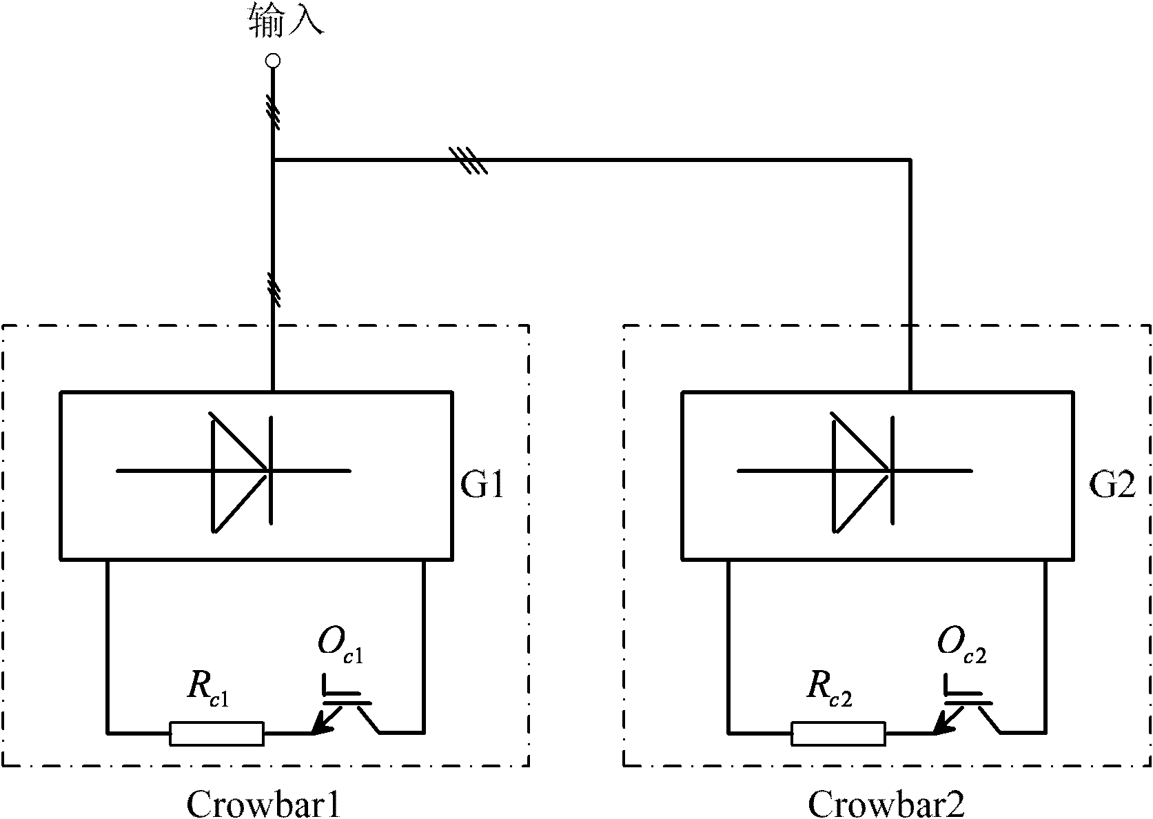
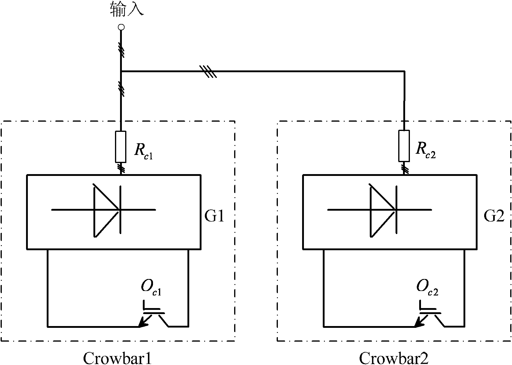
[0046] Embodiment 1 Taking the parallel connection of two crowbars as an example, it expounds the parallel crowbar structure using the typical structure of variable resistance crowbar and the parallel crowbar structure algorithm of the matching typical structure of variable resistance crowbar. And the process of reducing the steady-state current when the motor runs asynchronously after a large slip series Crowbar resistor is as described in the above steps. The reason why it can realize the purpose of the invention is that the variable resistance input of the Crowbar can be realized through the above-mentioned control algorithm. In the specific implementation process of the parallel crowbar structure algorithm of the typical variable resistor crowbar structure, when it is judged that there is a grid voltage drop, the parallel crowbar control is started. When it is judged that there is an overvoltage of the busbar voltage or an overcurrent of the rotor current, control Crowbar1...

Embodiment 2

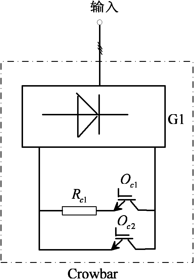
[0060] Embodiment 2 Taking the chopping crowbar structure composed of two controllable devices as an example, the chopping crowbar structure using the typical structure of the variable resistance crowbar and the control algorithm of the chopping crowbar structure with the typical structure of the variable resistance crowbar are explained. In , when it is judged that there is a grid voltage drop, the parallel Crowbar control is started. When it is judged that there is bus voltage overvoltage or rotor current overcurrent, control O c1 closed, the Crowbar bleeds resistor R c1 into the rotor circuit in series, and at the same time at O c1 During the closing period, send a high-frequency pulse signal with a set duty cycle to control the device O c2 , to make closing or opening, when the controllable device O c2 When closed, the controllable device O c1 and bleeder resistor R c1 loops in series or be short-circuited (see image 3 ) or with the controllable device O c2 and ble...


PUM


Abstract

The invention discloses two variable resistor Crowbar structures for the low-voltage ride-through of wind power generation and a method for realizing the variable resistor Crowbar structures. A parallel Crowbar structure comprises two or more than two Crowbars which are connected in parallel and have the very same structure. In a chopped Crowbar structure, two or more than two controllable devices are connected in parallel with an output loop of an uncontrolled bridge, wherein at least one controllable device is connected in series with a bleeder resistor. The method comprises the following steps of: detecting a three-phase grid voltage, a three-phase rotor current and a direct current bus voltage; converting the three-phase grid voltage and the three-phase rotor current to obtain a grid voltage and a rotor current under a two-phase stationary coordinate system, and computing amplitude values of the grid voltage and the rotor current; and by input of the amplitude values of the grid voltage and the rotor current and the direct current bus voltage, and by using a parallel Crowbar structure algorithm or a chopped Crowbar structure algorithm of the variable resistor Crowbar structures with corresponding structures, acquiring control signals of the Crowbars to control the on and off of the controllable devices of the Crowbars respectively.

Description

technical field [0001] The invention relates to a variable resistance Crowbar structure for wind power generation low-voltage ride-through and a realization method thereof. Background technique [0002] With the continuous increase of wind power installed capacity and the increasing technical level of wind power machine manufacturers and component manufacturers, the ability of wind power units to cope with grid failures has gradually become the focus of attention. Among them, the low-voltage ride-through function of wind turbines, especially doubly-fed wind turbines, has become the focus of wind farms because of its difficulty in implementation and verification. Based on this requirement of wind farms, manufacturers of various components of wind turbines include the low voltage ride through function in their functional characteristics. In response to this requirement, a variety of solutions have emerged in the industry. For example, the patent application No. 201010173894....

Claims


Application Information

Patent Timeline
Patent Type & Authority Applications(China)
IPC IPC(8): H02P9/10H02J3/38
CPCY02E10/76
Inventor 郑艳文龚细秀苑国锋
Owner 北京清能华福风电技术有限公司
Why Eureka
Try Eureka