Method for machining reduced copper capillary tube used in air conditioner

A copper capillary and air-conditioning device technology, which is applied in the field of copper capillary variable diameter processing, can solve the problems of easy welding and plugging capillary, high cost, increased material cost, etc., and achieve smooth and round inner and outer surfaces, low production cost, and excellent straightness Effect

Active Publication Date: 2011-10-26
GOLDEN DRAGON PRECISE COPPER TUBE GROUP +1
View PDF4 Cites 16 Cited by
  • Summary
  • Abstract
  • Description
  • Claims
  • Application Information

AI Technical Summary

Problems solved by technology

There are mainly two ways to connect the existing shunt capillary to the heat exchange tube: one is to weld a copper tube between the shunt capillary and the heat exchange tube. It needs to be deformed, and the appearance effect is poor. Because the connecting copper tube is relatively thick, it is often restricted in structure; 2. Because the inner diameter of the capillary is small, it is easy to weld and block the capillary during the welding process; 3. Through the transition connection of the copper tube, the two copper tubes There is a brazing joint at each end, there is a quality risk of welding joint leakage, and at the same time increases material costs and affects production efficiency
The other is to use variable-diameter capillary tubes to connect with heat exchangers, but the current variable-diameter capillary tubes are mainly produced by stretching. The stretching method to prepare variable-diameter copper capillary tubes is low in efficiency and high in cost, and cannot meet customer requirements.

Method used


Image

  • Method for machining reduced copper capillary tube used in air conditioner
  • Method for machining reduced copper capillary tube used in air conditioner
  • Method for machining reduced copper capillary tube used in air conditioner

Examples


Embodiment 1

[0025] The copper capillary blank is: the outer diameter is 4mm, the inner diameter is 3mm, and the length is L;

[0026] Processing requirements: the length of the big end is 8mm, and the outer diameter is 6.35mm.

[0027] The specific processing steps are as follows:

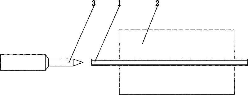
[0028] Such as figure 1 as shown, The first step: place the copper capillary blank 1 in the tightening tooling 2 of the hydraulic clamping device, use a punch 3 with an outer diameter of 4.2mm to squeeze the end of the capillary, and perform the first expansion (about 15mm in length). The inner diameter of the tube 11 at the rear end of the mouth is 4.2mm; the outer diameter is 5.3mm. Before flaring, lubricating oil should be applied to the end 11 of the expanded end. The lubricating oil used in this example is: Idemitsu series products from Japan, and the product model is Idemitsu 560. During this process, the oil pressure in the hydraulic clamping device is 8Mpa.

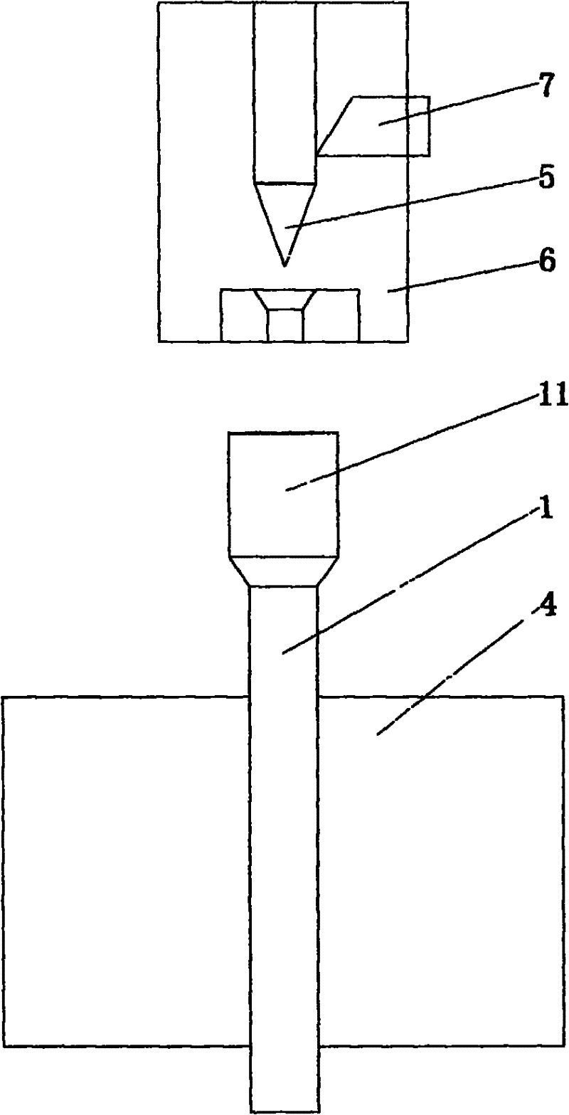
[0029] Such as figure 2 as shown,...

Embodiment 2

[0031] The copper capillary blank is: the outer diameter is 4.5mm, the inner diameter is 3mm, and the length is L;

[0032] Processing requirements: the length of the big end is 8mm, and the outer diameter is 7.0mm.

[0033] The specific processing steps are as follows:

[0034] Such as figure 1 as shown, The first step: place the copper capillary blank 1 in the tightening tooling 2 of the hydraulic clamping device, punch the end of the capillary with a punch 3 with an outer diameter of 4.5mm, and perform the first expansion (about 15mm in length). The inner diameter of the 11 tubes at the rear end of the mouth is 4.5 mm; the outer diameter is 6.0 mm. Before flaring, lubricating oil should be applied to the end 11 of the expanded end. The lubricating oil used in this example is: Idemitsu series products from Japan, and the product model is Idemitsu 560. During this process, the oil pressure in the hydraulic clamping device is 8Mpa.

[0035] Such as figure 2 as shown,...

Embodiment 3

[0037] The copper capillary blank is: the outer diameter is 6.35mm, the wall thickness is 0.7mm, and the length is L;

[0038] Processing requirements: the length of the big end is 7mm, and the outer diameter is 9.52mm.

[0039] The specific processing steps are as follows:

[0040] Such as figure 1 as shown, The first step: place the copper capillary blank 1 in the tightening tooling 2 of the hydraulic clamping device, use a punch 3 with an outer diameter of 6.5mm to squeeze the end of the capillary, and perform the first flaring (length about 15mm). The inner diameter of the 11 tubes at the rear end of the mouth is 6.5 mm; the outer diameter is 8.1 mm. Before flaring, lubricating oil should be applied to the end 11 of the expanded end. The lubricating oil used in this example is: Idemitsu series products from Japan, and the product model is Idemitsu 560. During this process, the oil pressure in the hydraulic clamping device is 9Mpa.

[0041] Such as figure 2 as sho...


PUM

PropertyMeasurementUnit
lengthaaaaaaaaaa
sizeaaaaaaaaaa
sizeaaaaaaaaaa

Abstract

The invention relates to a method for machining a reduced copper capillary tube used in an air conditioner. The method comprises the following steps of: 1) horizontally putting a copper capillary tube blank into a tensioning tooling of a hydraulic clamping device, carrying out impact extrusion on one end of the copper capillary tube by using a flaring punch in a flaring device for the first-time flaring; and 2) leading the flared end of the copper capillary tube to face upwards, vertically placing the copper capillary tube in a tensioning tooling of a pneumatic clamping device, carrying out impact extrusion on the flared end of the copper capillary tube by a flaring punch in a spinning flaring device for the second-time flaring; and simultaneously, cutting residual part of the copper capillary tube by utilizing a turning tool additionally arranged on a seat sleeve of the spinning flaring device, thus obtaining a reduced copper capillary tube with a set dimension. The machining method is adopted to directly flare the copper capillary tube to obtain the product, so that the production efficiency is high, the yield rate is high and the production cost is low. The reduced copper capillary tube manufactured by adopting the machining method is even in wall thickness, and excellent in linearity, and has smooth and round internal and external surfaces.

Description

technical field [0001] The invention relates to copper capillary tubes for air conditioners, in particular to a copper capillary tube reducing diameter processing method used in air conditioners. Background technique [0002] In the existing air conditioner heat exchanger, in order to make the heat exchange uniform and improve the heat exchange efficiency, the heat exchanger is often designed as a multi-circulation flow path, and the different flow paths are connected through the shunt capillary connected to it. The shunt capillary can make The flow of refrigerant on different flow paths of the circulation system is even, which improves the heat exchange efficiency of the heat exchanger. There are mainly two ways to connect the existing shunt capillary to the heat exchange tube: one is to weld a copper tube between the shunt capillary and the heat exchange tube. It needs to be deformed, and the appearance effect is poor. Because the connecting copper tube is relatively thic...

Claims


Application Information

Patent Timeline
Patent Type & Authority Applications(China)
IPC IPC(8): B21D41/02
Inventor 王伟李秀成陈永光丁玉强李东方杨安山毕永飞王凤宇
Owner GOLDEN DRAGON PRECISE COPPER TUBE GROUP
Why Eureka
Try Eureka