
Drill string equipped with downhole blowout preventer and working method thereof

A blowout preventer and drill string technology, applied in the direction of drill pipe, drill pipe, drilling equipment, etc., can solve the problems of inability to provide early warning and blowout prevention, increase the pressure difference of downhole annular space, and slow signal transmission speed, etc., and achieve The transmission speed is fast, the blowout accident is prevented, and the method is simple and feasible.

Inactive Publication Date: 2011-10-26
SOUTHWEST PETROLEUM UNIV
View PDF9 Cites 11 Cited by
  • Summary
  • Abstract
  • Description
  • Claims
  • Application Information

AI Technical Summary

Problems solved by technology

Serious accidents will occur if the operator is inexperienced or negligent at work and fails to detect signs of well kick or blowout in time
Moreover, the traditional wellhead blowout preventer takes a long time to replace the mud and kill the well after the well shut-in operation, which will cause more bottom fluid to invade the wellbore, increase the downhole annular pressure difference, and thus increase the control of blowout. difficulty, at the same time, the traditional signal transmission is realized by mud pulse, which is mainly to add a mud pulse generator in the middle of the mud circulation pipeline for two-way communication, so whether it is the acquisition of downhole signals or the control of subsequent blowout prevention, the other The transmission speed of the signal is relatively slow, and it takes a long time, so it cannot achieve the effect of early warning and blowout prevention at all.

Method used


Image

  • Drill string equipped with downhole blowout preventer and working method thereof
  • Drill string equipped with downhole blowout preventer and working method thereof
  • Drill string equipped with downhole blowout preventer and working method thereof

Examples


Embodiment Construction

[0043] All features disclosed in this specification, or steps in all methods or processes disclosed, may be combined in any manner, except for mutually exclusive features and / or steps.

[0044] Any feature disclosed in this specification (including any appended claims, abstract and drawings), unless expressly stated otherwise, may be replaced by alternative features which are equivalent or serve a similar purpose. That is, unless expressly stated otherwise, each feature is one example only of a series of equivalent or similar features.

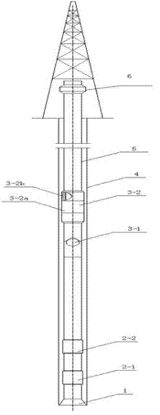
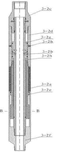
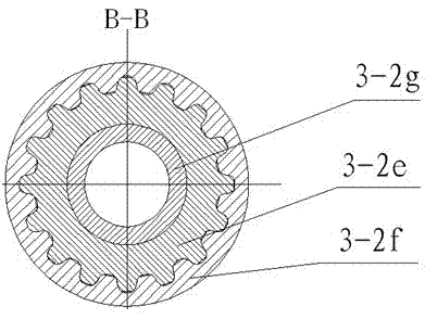
[0045] The drill string that the downhole blowout preventer of the present invention is installed, as figure 1 , figure 2 and image 3As shown, a drill bit 1 is arranged on the drill string body, and a downhole blowout preventer 3 is arranged on the drill string body, and the downhole blowout preventer 3 is installed at a position above the neutral point of the drill string body. According to actual needs, choose not to install above the n...


PUM


Abstract

The invention discloses a downhole blowout prevention technology and belongs to the technical field of downhole blowout prevention. The invention relates to a drill string equipped with a downhole blowout preventer, and the drill string comprises a drill string body, wherein a drill bit is arranged at the bottom of the drill string body. The drill string is characterized in that the downhole blowout preventer is mounted on the drill string body, at least one pressure monitoring and signal generating device is arranged at one end, adjacent to the drill bit, of the drill string body, a signal receiving and alarm generating device is arranged at the upper part of the top of the drill string body, and the signal receiving and alarm generating device is matched with the pressure monitoring andsignal generating device. By adopting the drill string equipped with the downhole blowout preventer, downhole well kick or blowout can be effectively monitored; and furthermore, the alarm signal transfer speed is fast, measures can be timely and effectively adopted for implementing well sealing, the blowout preventer is positioned above a neutralization point, the blowout preventer is in a tension state, the purposes of placing a pipe column downwards for setting and lifting the pipe column upwards for unsealing can be realized, and the well kick or the blowout can be effectively prevented.

Description

technical field [0001] The invention relates to a blowout prevention technology when well kick and blowout occur in the drilling process of oil and gas fields. Background technique [0002] Drilling plays a very important role in various tasks of oil exploration and oil field development, such as finding and confirming oil and gas structures, obtaining industrial oil flows, ascertaining the oil and gas bearing areas and reserves of proven oil and gas structures, and obtaining relevant The geological data and development data of the oil field, and finally the crude oil is taken from the ground to the ground, etc. are all completed by drilling. Drilling is an important link in the exploration and exploitation of oil and natural gas resources, and an important means of oil exploration and development. . [0003] During the drilling process, when drilling into oil and gas layers, if the bottom hole pressure is lower than the formation pressure, the formation fluid will enter th...

Claims


Application Information

Patent Timeline
IPC IPC(8): E21B17/00E21B33/06E21B47/06E21B47/12E21B47/10
Inventor 刘清友黎伟
Owner SOUTHWEST PETROLEUM UNIV
Learn More