Testing apparatus for evaluating drag-reduction effects of bionic non-smooth surface and bionic jet surface

A non-smooth surface, test device technology, used in fluid dynamics tests, measuring devices, testing of machine/structural components, etc., can solve problems such as drag reduction, difficult maintenance, and cumbersome operations, and achieve lower operating costs. The effect of working reliability, simple replacement process

Inactive Publication Date: 2011-10-26
HARBIN ENG UNIV
View PDF3 Cites 36 Cited by
  • Summary
  • Abstract
  • Description
  • Claims
  • Application Information

AI Technical Summary

Problems solved by technology

In the traditional fluid dynamics research, the water tunnel test device is mainly used, but its volume is large, the cost is high, the operation is cumbersome, the control of test conditions is difficult, and the test model is complicated
The number of existing pools in our country is limited, the construction of well-equipped pools is expensive, the daily maintenance is difficult, and the test cost is high. Generally, it is only studied for some large-scale tests in the country and cannot be widely used.
Existing small-scale fluid mechanics test equipment

Method used


Image

  • Testing apparatus for evaluating drag-reduction effects of bionic non-smooth surface and bionic jet surface
  • Testing apparatus for evaluating drag-reduction effects of bionic non-smooth surface and bionic jet surface
  • Testing apparatus for evaluating drag-reduction effects of bionic non-smooth surface and bionic jet surface

Examples


Embodiment Construction

[0036] The specific implementation process of the present invention will be described below in conjunction with the accompanying drawings.

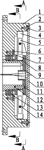
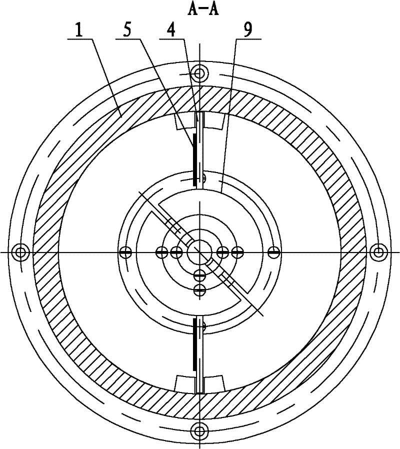
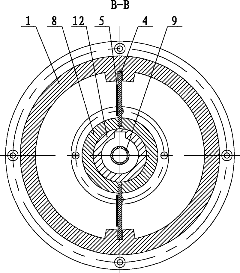
[0037] In the figure: 1. Sensor shell, 2. Sealing gasket, 3. Countersunk screw, 4. Driving lever, 5. Strain gauge, 6. Countersunk screw, 7. Bearing end cover, 8. Driving lever bracket, 9. Baffle, 10. Sealing end cover, 11. Countersunk head screw, 12. Sensor inner shell, 13. Bearing, 14. Cable, 15 Water tank, 16. Sealing gasket, 17. Countersunk head screw, 18. Bearing end cover , 19. Sealing end cover, 20. Jet inlet pipeline, 21. Sealing gasket, 22. Bearing, 23. Sealing gasket, 24. Waterproof bearing, 25. Permanent magnet (N-S), 26. Pole plate, 27. Countersunk screw, 28. Right end cover of sealing chamber, 29. Jet seal, 30. Countersunk screw, 31. Test sample, 32. Bolt, 33. Sealing gasket, 34. Sealing chamber, 35. Elastic retainer for shaft Ring, 36. Sealing shaft, 37. End cover of sealing body, 38. Retaining ring for hole, 39. Retaining r...


PUM


Abstract

The invention provides a testing apparatus for evaluating the drag-reduction effects of a bionic non-smooth surface and a bionic jet surface. The testing apparatus comprises a sealing shaft, a power input and signal output mechanism, a sensor mechanism, a gas-tight silo and a water distribution mechanism, wherein the power input and signal output mechanism is arranged at one end of the sealing shaft, the sensor mechanism is arranged at the other end of the sealing shaft, and the gas-tight silo surrounds the sensor mechanism. The testing apparatus provided by the invention is suitable to be used for testing the drag-reduction effects of a non-smooth surface and a surface coating as well as a bionic jet surface; and a data acquisition system is simple in structure, easy to operate, and accurate in testing. By using the testing apparatus provided by the invention, both the drag-reduction effect of a non-smooth surface and the drag-reduction effect of a jet surface structure also can be evaluated. The fluid friction resistance values of the testing apparatus under different test sample conditions are acquired by using the data acquisition system, and then the data comparison is performed so as to obtain the drag-reduction effects of different surface structures, thereby studying the drag-reduction characteristics of a non-smooth surface structure and a jet surface structure.

Description

technical field [0001] The invention relates to a test device capable of testing the frictional resistance of fluid to different surface structures, and is especially suitable for testing the drag-reducing effect of non-smooth surface structures and surface coatings, and testing the drag-reducing effect of bionic jet surfaces. Background technique [0002] The current test devices for testing fluid friction resistance mainly include test devices such as water holes, pools, and drags. As an important means of studying fluid drag reduction, test methods play a vital role in promoting the development of fluid drag reduction theory. Many important phenomena of fluids are first obtained under test conditions. With the rapid development of drag reduction technology, how to design a test device that can evaluate the frictional resistance of fluid to different surface structures is particularly important. In the traditional fluid dynamics research, the water tunnel test device is m...

Claims


Application Information

Patent Timeline
IPC IPC(8): G01M10/00
Inventor 赵刚谷云庆夏冬来赵华琳舒海生赵丹谢志超杨立明刘浩韩毛毛
Owner HARBIN ENG UNIV
Why Eureka
Try Eureka