Inverter control device and inverter control method
A converter control and transformer technology, applied in the direction of output power conversion device, AC power input conversion to DC power output, manufacturing tools, etc., can solve the problems of transformer saturation, switching elements cannot be fully driven, and difficult high-precision micro-current Control and other issues to achieve the effect of controlling the output current
- Summary
- Abstract
- Description
- Claims
- Application Information
AI Technical Summary
Problems solved by technology
Method used
Image
Examples
Embodiment approach 1
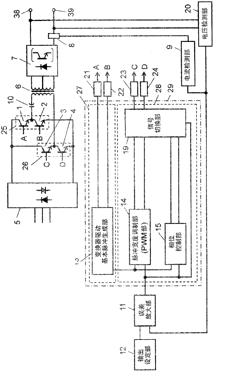
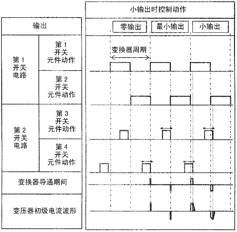
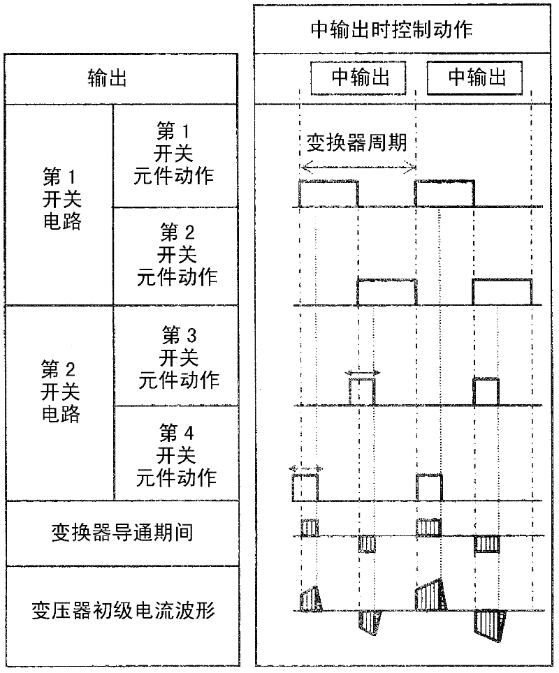
[0109] use figure 1 and Figure 2A -C describes the arc welding machine using the inverter control device according to the first embodiment. figure 1 The schematic structure of the main part of the arc welding machine in this Embodiment 1 is shown. Figure 2A -C is a schematic diagram which shows the operation|movement of the structural part of the arc welding machine of this Embodiment 1. Figure 2A ~C are diagrams for explaining the operation of the arc welding machine, each showing the case where the welding output is small ( Figure 2A ), in the case of the output ( Figure 2B ) and in the case of large output ( Figure 2C ), the action of the switching element, the conduction period of the converter and the primary current waveform of the transformer.
[0110] In addition, the distinction among the small output, the middle output, and the large output among welding outputs is performed based on the magnitude|size of the error amplification signal from the error amp...
Embodiment approach 2
[0143] use image 3 and Figure 4A -C demonstrates the arc welding machine which employs the inverter control apparatus of this Embodiment 2. FIG. image 3The schematic structure of the main part of the inverter control apparatus of the arc welding machine in this Embodiment 2 is shown. Figure 4A to C are used to describe the operation of the inverter control device of the arc welding machine according to the second embodiment. Indicates: when the welding output is a small output ( Figure 4A ), in the case of the output ( Figure 4B ) and in the case of large output ( Figure 4C ) In the converter control device, the action of the switching element, the converter conduction period, and the transformer primary current waveform.
[0144] In addition, in this embodiment, the same structure and the same part as Embodiment 1 are attached|subjected by the same code|symbol, and detailed description is abbreviate|omitted.
[0145] The main difference from the first embodiment ...
Embodiment approach 3
[0178] use Figure 5 The inverter control device of the arc welding machine according to Embodiment 3 will be described through FIG. 7 . Figure 5 The schematic structure of the main part of the inverter control apparatus of the arc welding machine in this Embodiment 3 is shown. Figure 6A -C is a schematic diagram for demonstrating the operation|movement of the inverter control apparatus of the arc welding machine of this embodiment. Respectively represent the case where the welding output is a small output ( Figure 6A ), in the case of the output ( Figure 6B ) and in the case of large output ( Figure 6C ), the action of the switching element, the conduction period of the converter and the primary current waveform of the transformer. Figure 7A , B is an explanatory diagram of the operation of the converter, showing changes in the operating state. Figure 7A Represents the entire waveform of 1 cycle, and Figure 7B shows Figure 7A The conduction state of the switchin...
PUM
 Abstract
Description
Claims
Application Information
 - R&D
- Intellectual Property
- Life Sciences
- Materials
- Tech Scout
- Unparalleled Data Quality
- Higher Quality Content
- 60% Fewer Hallucinations
Browse by: Latest US Patents, China's latest patents, Technical Efficacy Thesaurus, Application Domain, Technology Topic, Popular Technical Reports.
© 2025 PatSnap. All rights reserved.Legal|Privacy policy|Modern Slavery Act Transparency Statement|Sitemap|About US| Contact US: help@patsnap.com


