Bathtub overflow/drainage control device

A technology for a control device and a bathtub, applied to water supply devices, valve operation/release devices, valve devices, etc., can solve problems such as troublesome installation, use and maintenance of devices, achieve simple structure, good versatility, and increase water storage capacity Effect

Active Publication Date: 2011-11-02
KOHLER CHINA INVESTMENT
View PDF10 Cites 7 Cited by
  • Summary
  • Abstract
  • Description
  • Claims
  • Application Information

AI Technical Summary

Problems solved by technology

Moreover, the drainage and overflow devices of the bathtub are all independent and installed separately, which brings great trouble to the installation, use and maintenance of these devices.

Method used


Image

  • Bathtub overflow/drainage control device
  • Bathtub overflow/drainage control device
  • Bathtub overflow/drainage control device

Examples


Embodiment Construction

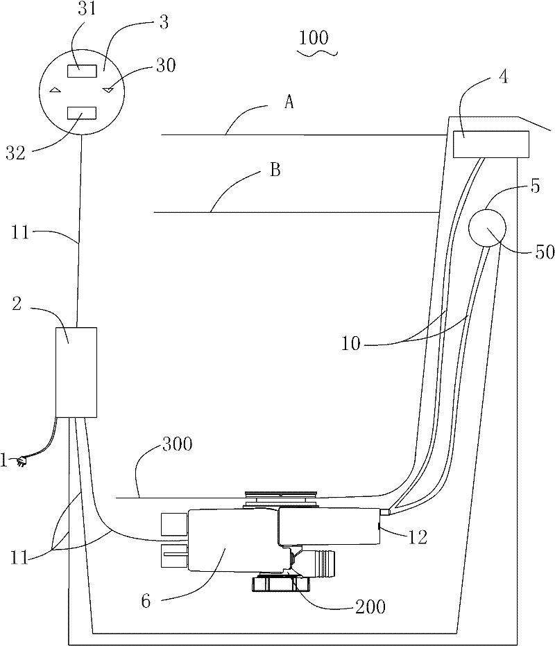
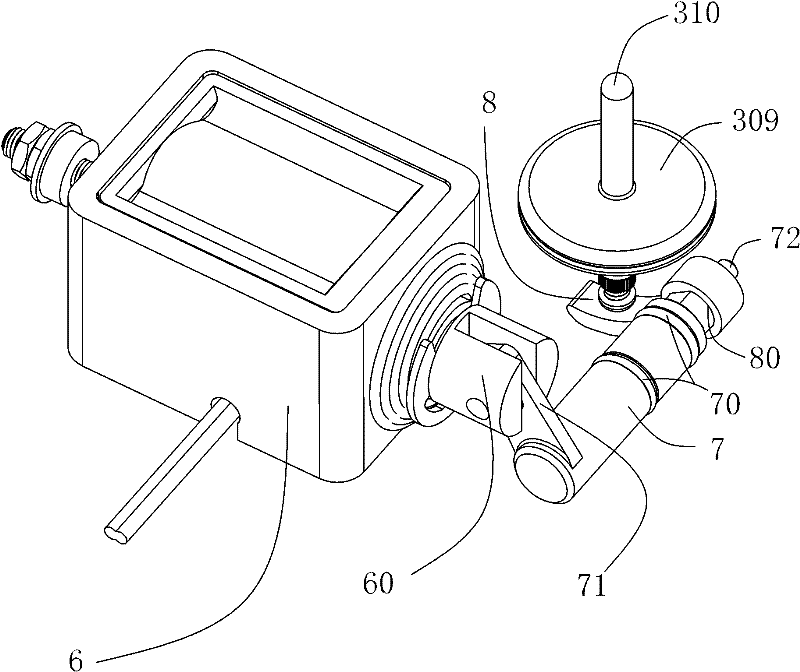
[0031] Such as figure 1 , figure 2 The control device 100 for the overflow and drainage of the bathtub of the present invention shown includes a power plug 1, a controller 2, a control panel 3, a water level protection switch 4, a water level sensor 5, an electromagnetic valve 6 connected to the drain seat 200, and an electromagnetic valve. The rotating shaft 7 connected with the valve 6, the top claw 8 connected with the rotating shaft 7, and a pair of water delivery pipes 10 and several power transmission lines 11 respectively connected with the water level protection switch 4 and the water level sensor 5.

[0032] The drain seat 200 is provided with a temperature sensor 12 .

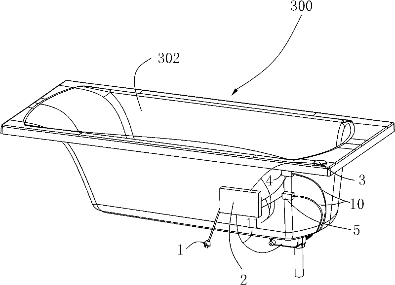
[0033] Such as Figure 3 to Figure 5 As shown, the bathtub 300 has a flat bottom 301 and a continuous side wall 302 formed around the bottom 301 , and a drain 303 connecting the inside and outside of the bathtub 300 is provided in the middle of one end of the bottom 301 . The side wall 302 of the ...


PUM


Abstract

The invention relates to a bathtub overflow / drainage control device connected with a bathtub, which comprises a power plug, a transmission line, a controller, a control panel, a water level induction apparatus and a closed apparatus provided with a drive device; the closed apparatus comprises a valve box connected to the bathtub drainage position, a rotating shaft which is arranged in the valve box and driven by the drive device, a top claw and a water plug connected with the valve box; and the water plug is driven by the top claw and at least has a closed position and an open position. The control device can be operated in a simple and reliable way, and has great flexibility in the aspects of connection and composition of the bathtub and drainage pipe.

Description

【Technical field】 [0001] The present invention relates to a combined overflow and drain control device for use on a bathtub for moving a closing element for closing the drain opening, in particular of a bathtub. 【Background technique】 [0002] Existing bathtubs have a mechanical moving device for moving the closure element that closes the bathtub drain, the device includes an operating knob mounted on the bathtub, which, if turned by the user of the bathtub, moves the closure element from an open position to a closed position. Position or move in the opposite direction, in this regard, the rotary movement of the operating knob is converted into a linear movement of the closure element, for example by means of a cable connection. However, a disadvantage with regard to the cable connection is that, in unfavorable installation positions, the twisting of the cable makes actuation of the control knob considerably more difficult. Furthermore, the wire-guy connection limits the po...

Claims


Application Information

Patent Timeline
IPC IPC(8): E03C1/232A47K1/14F16K31/06
Inventor 朱伟辉陈国锋
Owner KOHLER CHINA INVESTMENT
Why Eureka
Try Eureka