Heating floor formed by connecting metal heat-transfer element and heating element at low thermal resistance

A heating element and low thermal resistance technology, which is applied in the field of heating floors and heat pipes, can solve the problems such as the difficulty of ensuring the surface contact heat exchange state, the small heat transfer area between the floor heating pipes and the floor, the use of keels and floor heating pipes, etc., so as to save wood. , the effect of preventing termite erosion and optimizing mechanical properties

Inactive Publication Date: 2011-11-02
HAINING IEMYC SOLAR ENERGY TECH
View PDF2 Cites 6 Cited by
  • Summary
  • Abstract
  • Description
  • Claims
  • Application Information

AI Technical Summary

Problems solved by technology

The distance between the keels of this scheme is only the width of the floor, and the usage of keels and floor heating pipes is too much; too many slots on the floor of the two-story structure greatly reduce the mechanical strength and affect the use and cost of materials; metal materials are not suitable for "hot pressing" and Wood connection; the heat transfer area between the floor heating pipe and the floor is small, and the floor is easily deformed due to the inconvenience of no grooves and nails, and the non-fixed connection between the floor heating pipe and the floor makes it difficult to guarantee the surface contact heat exchange state between the two; The overall strength of the keel with rows of holes and slots is reduced, and it is easy to crack during installation

Method used


Image

  • Heating floor formed by connecting metal heat-transfer element and heating element at low thermal resistance
  • Heating floor formed by connecting metal heat-transfer element and heating element at low thermal resistance
  • Heating floor formed by connecting metal heat-transfer element and heating element at low thermal resistance

Examples


Embodiment Construction

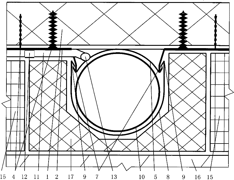
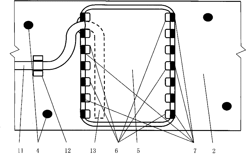
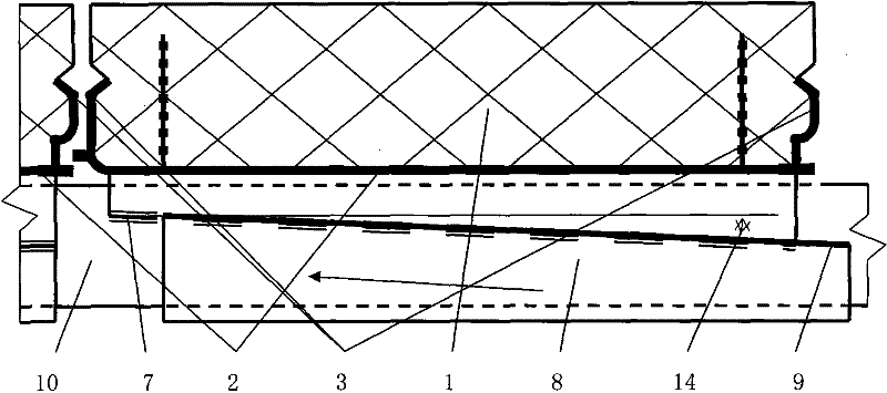
[0034] Figure 1~3 A first embodiment of the present invention is collectively given. Figure 1~3 Among them, the metal heat conduction plate 2 arranged on the lower surface of the floor panel 1 wraps the floor panel 1 from both sides with the wrapping 3 to realize a fixed low thermal resistance connection with the floor panel 1 . The metal heat conducting plate 2 and the ground plate 1 are also connected by silica gel bonding and screws 4 with low thermal resistance. The metal heat conducting plate 2 presses down a groove 5 , and the groove 5 contains two rows of fixed flanges 7 formed by flange holes 6 . Fixed flange 7 utilizes the material that flange hole 6 turns over on groove 5 to make, and a plurality of fixed flanges 7 are arranged in a row. The fixed flange 7 hooks up the two connecting flanges 9 of the U-shaped cover plate 8 . The trough 5 on the metal heat conducting plate 2 and the U-shaped cover plate 8 wrap and connect the hot water pipe 10 together with low t...


PUM


Abstract

The invention relates to a heating floor formed by connecting a metal heat-transfer element and a heating element at low thermal resistance. The heating floor comprises a floor, a metal heat-conducting plate connected with the lower surface of the floor and a heating element connected with the metal heat-conducting plate at low thermal resistance. The heating floor is characterized in that the metal heat-conducting plate is connected with the floor by one of the following three manners or the combination of the three manners at low thermal resistance: (1) connecting by using a nail connecting member; (2) bonding; and (3) wrapping joining of the metal heat-conducting plate. The invention has the advantages that the metal heat-conducting plate is connected with the floor by using a nail-shaped connecting member, bonding and wrapping joining, the thermal resistance between the floor and the metal heat-conducting plate can be reduced, and the strength of the floor can be enhanced. A heating pipe can greatly increase the heat-transfer efficiency of the metal heat-conducting plate, increase the heat-transfer distance, and reduce differences in temperature and the quantity of the heating element. The 5-10 DEG C heat-transfer temperature drop from the heating element to the floor can be reduced, and the thermal resistance of a dry heating floor can be reduced to an ideal degree. Five embodiments are given by combining figures.

Description

technical field [0001] The invention relates to a heating floor and a heat pipe technology which are connected with a heating element through a metal heat transfer element with low thermal resistance. Background technique [0002] The keel solid wood floor feels comfortable. Heating with floor heating can obtain a comfortable temperature gradient of warming at the bottom and cooling at the top, and is suitable for using heat energy below 60°C provided by solar collectors and heat pump units. [0003] In the existing wet-type heating floor, an insulating layer is arranged on the floor, concrete with embedded heating pipes is laid on the insulating layer, and a floor plate is laid on the concrete. The heated concrete radiates heat to the interior through the floor slab. The wet heating floor has a large thermal inertia, the structural layer takes up a lot of space, the walking comfort is low, maintenance is difficult, and its wooden floor panels are easily deformed. For thi...

Claims


Application Information

Patent Timeline
Patent Type & Authority Applications(China)
IPC IPC(8): E04F15/02E04F15/18F24D13/00
Inventor 施国樑
Owner HAINING IEMYC SOLAR ENERGY TECH
Why Eureka
Try Eureka