High-temperature resistant centrifugal fan

A centrifugal fan, high temperature resistant technology, applied in the direction of mechanical equipment, machine/engine, liquid fuel engine, etc., can solve the problems of cooling the impeller hub, unable to cool and protect the fan impeller, and unable to eliminate the impeller rivet loosening, etc.

Active Publication Date: 2011-11-02
SHANDONG LINFENG TECH
View PDF6 Cites 5 Cited by
  • Summary
  • Abstract
  • Description
  • Claims
  • Application Information

AI Technical Summary

Problems solved by technology

[0008] The above-mentioned existing technologies mostly adopt air cooling and forced cooling to cool the main shaft and bearings, but the hub of the impeller cannot be cooled, and the rivets of the hub and

Method used


Image

  • High-temperature resistant centrifugal fan
  • High-temperature resistant centrifugal fan
  • High-temperature resistant centrifugal fan

Examples


Embodiment Construction

[0029] In order to deepen the understanding of the present invention, the present invention will be further described below in conjunction with the examples and accompanying drawings. The examples are only used to explain the present invention and do not constitute a limitation to the protection scope of the present invention.

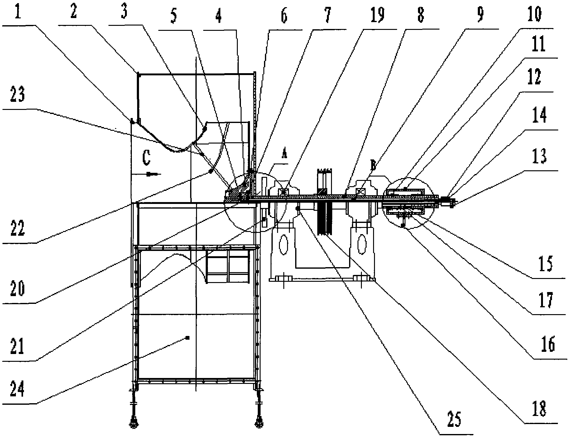
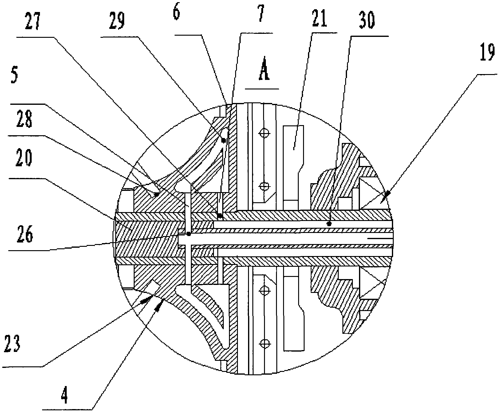
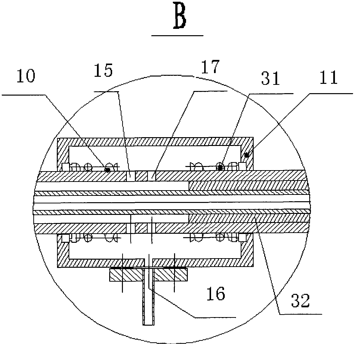
[0030] Such as figure 1 As shown, a high-efficiency high-temperature-resistant centrifugal fan includes a fan body, a transmission group 25, a rotary joint 12, and a cooling medium collector 34; wherein the fan body includes a casing 2, an air inlet 1, an impeller 3, and a hub 4. The wheel disc and air outlet 24; the transmission group 25 includes the main shaft 8 and the pulley 18; the rotary joint 12 is provided with a cooling medium inlet 13 and a rotary joint seal 14;

[0031] Wherein the main shaft 8 is a hollow structure, one end of the main shaft 8 is installed with the impeller 3 through the impeller hub, and the other end is connected with the...


PUM


Abstract

The invention discloses a high-temperature resistant centrifugal fan, comprising a fan body, a driving group, a rotary joint and a cooling medium collector, wherein the fan body comprises an enclosure, a wind inlet, an impeller, a hub, a wheel disc and a wind outlet; the driving group comprises a main shaft and a belt wheel; the rotary joint is provided with a cooling medium inlet and a rotary joint seal; the main shaft is in a hollow structure, one end of the main shaft is connected with the hub of the impeller, and the other end of the main shaft is connected with the rotary joint; a core pipe is arranged inside the main shaft; an annular cavity is formed between the main shaft and the core pipe; the hub is in a hollow structure, and a hollow cavity is formed in the hub; the joint between the main shaft and the hub is provided with a cooling medium path; and the cooling medium enters the core pipe from a cooling medium inlet positioned on the rotary joint and is introduced into the hub via the cooling medium path to be cooled. According to the high-temperature resistant centrifugal fan disclosed by the invention, the fan can bear 1000-DEG C high-temperature gas delivery due to the hollow structures of the main shaft and the hub and the cooling of the cooling medium.

Description

Technical field: [0001] The invention relates to a ventilation device, in particular to a high-efficiency centrifugal fan capable of transporting high-temperature gas. Background technique: [0002] Centrifugal fans are widely used in metallurgy, building materials, heat treatment, food and other fields due to their simple structure, low manufacturing cost, large flow rate of gas and high pressure. Independent support from the main shaft, coupled with structural features such as large width of the impeller, when the fan requires large flow and high pressure and the impeller rotates at a high speed, it is easy to cause the blade to bend and damage the machine; at the same time, when conveying high-temperature gas, due to the hub The unequal thickness of the disc and the coefficient of thermal expansion of the rivet or bolt can easily lead to loosening of the rivet or bolt, and the heat transfer of the high-temperature gas can also cause damage to the bearing. Therefore, gene...

Claims


Application Information

Patent Timeline
IPC IPC(8): F04D29/043F04D29/22F04D29/58
Inventor 王洪强盖京方
Owner SHANDONG LINFENG TECH
Why Eureka
Try Eureka