Industrial film digital once imaging system

An imaging system and film technology, which is applied in the direction of optical testing defects/defects, can solve the problems of staff's visual damage, low definition, long scanning time, etc., to avoid external light interference, expand the blackness range, and improve imaging effects Effect

Inactive Publication Date: 2011-11-02
白芳芳
View PDF5 Cites 2 Cited by
  • Summary
  • Abstract
  • Description
  • Claims
  • Application Information

AI Technical Summary

Problems solved by technology

[0002] The application of industrial ray detection to judge the weld defects of devices or products is very common. This judgment method is of great significance to the quality inspection of devices or products. Use a film lamp to observe the film developed by industrial radiography to judge the weld defects on the industrial film. This method is not only inefficient, but also easy to cause damage to the eyesight of the staff.
[0003] In order to improve work efficiency, the application number is: 201010013616.4, and the Chinese invention patent application titled: industrial radiation detection film digitization device provides a kind of industrial radiation detection film digitization device, but the device has the following defects: because the device uses linear scanning , resulting in the need for complex mechanical transmission during scanning, long scanning time and low resolution, and due to the use of mechanical transmission, the film does not have sufficient exposure time, resulting in the device being unable to meet the definition of industrial films with a blackness D greater than 4.0 Imaging requirements, in addition, mechanical transmission can easily cause industrial film to be scratched or worn, so that the original data cannot be well preserved

Method used


Image

  • Industrial film digital once imaging system
  • Industrial film digital once imaging system
  • Industrial film digital once imaging system

Examples


Embodiment Construction

[0026] The specific implementation manners of the present invention will be further described in detail below in conjunction with the accompanying drawings and embodiments. The following examples are used to illustrate the present invention, but are not intended to limit the scope of the present invention.

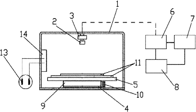
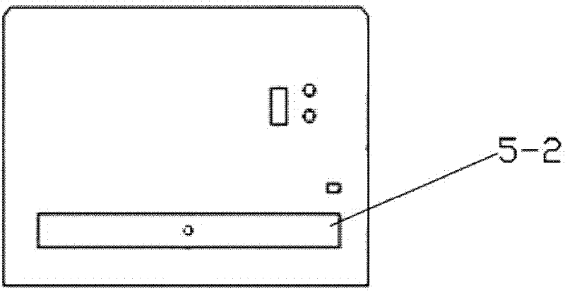
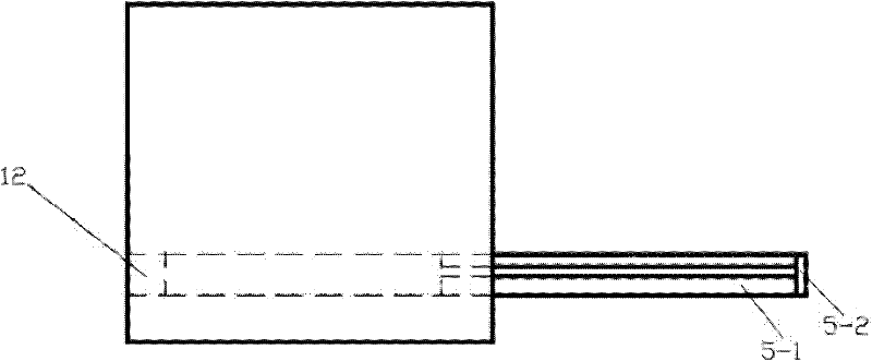
[0027] like Figure 1~3 As shown, the industrial film digital primary imaging system of the present embodiment includes: a housing 1, an optical lens 2, an image acquisition module 3, a cold light source 4 and a film delivery module 5 for sending an industrial film, and the optical lens 2 is set Above the inner side of the housing 1, the film feeding module 5 is arranged on the side of the housing 1 opposite to the optical lens 2, and the cold light source 4 is arranged below the inner side of the housing 1 and in the film feeding module 5 Directly below, the image acquisition module 3 is connected to the optical lens 2 for two-dimensional image acquisition, and converts ...


PUM


Abstract

The invention relates to the technical field of industrial nondestructive tests, in particular to an industrial film digital once imaging system. The system comprises a shell, an optical lens, an image acquisition module, a cold light source and a film feeding module which is used for feeding an industrial film, wherein the optical lens is arranged above the inner side of the shell; the film feeding module is arranged on the side edge of the shell opposite to the optical lens; the cold light source is arranged below the inner side of the shell and is positioned on the right lower side of the film feeding module; and the image acquisition module is connected with the optical lens and is used for acquiring a two-dimensional image and converting an optical signal acquired by the optical lens into a digital signal. The system improves the acquisition rate of the image and prevents the industrial film from moving through the image acquisition module capable of acquiring the two-dimensional image and the cold light source, so that the industrial film cannot be damaged, the blackness range of imaging the industrial film is expanded, and the requirement of digital imaging in the all blackness range of the industrial film is met; and an imaging effect is improved by arranging the shell, reducing light loss and avoiding interference of external light rays.

Description

technical field [0001] The invention relates to the technical field of industrial non-destructive testing, in particular to an industrial film digital primary imaging system. Background technique [0002] The application of industrial ray detection to judge the weld defects of devices or products is very common. This judgment method is of great significance to the quality inspection of devices or products. Use a film lamp to observe the film developed by industrial radiography to judge the weld defects on the industrial film. This method is not only inefficient, but also easy to cause damage to the eyesight of the staff. [0003] In order to improve work efficiency, the application number is: 201010013616.4, and the Chinese invention patent application titled: industrial radiation detection film digitization device provides a kind of industrial radiation detection film digitization device, but the device has the following defects: because the device uses linear scanning , r...

Claims


Application Information

Patent Timeline
Patent Type & Authority Applications(China)
IPC IPC(8): G01N21/88
Inventor 白芳芳李鹏
Owner 白芳芳
Why Eureka
Try Eureka