High-temperature superconductive magnetic suspension linear propulsion system with composite ontrack magnetizing function
A high-temperature superconducting and propulsion system technology, which is applied in the propulsion system, holding devices using magnetic attraction or thrust, electrical components, etc., can solve the problem of no high-efficiency magnetic levitation propulsion system, etc., and achieve advanced convenient efficiency and good system stability. , the overall performance is good
- Summary
- Abstract
- Description
- Claims
- Application Information
AI Technical Summary
Problems solved by technology
Method used
Image
Examples
Embodiment 2
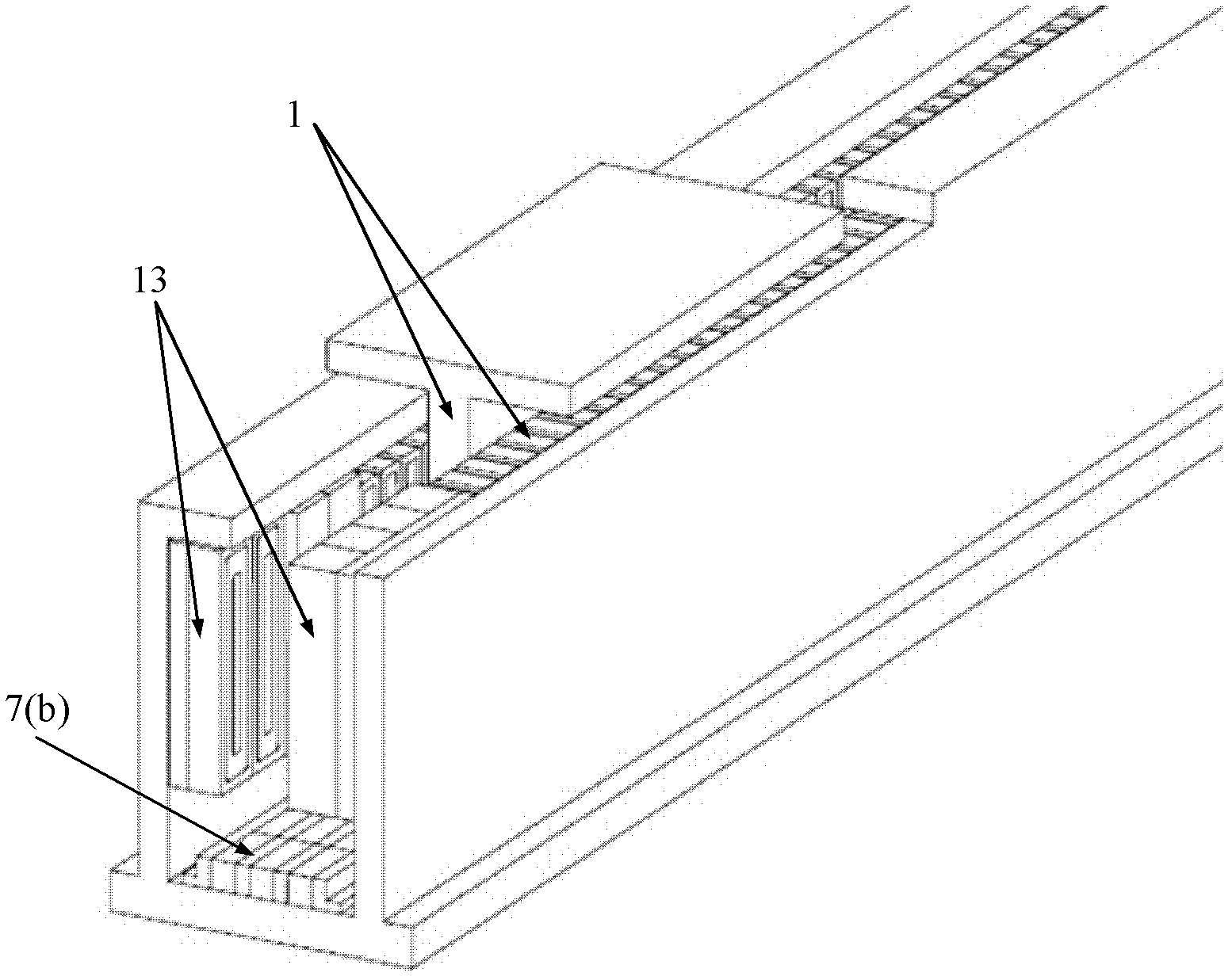
[0027] The overall structure of this embodiment two is basically the same as that of embodiment 1, as image 3 , 4 and Figure 6 As shown, it consists of a bilateral high-temperature superconducting linear synchronous motor 1, a high-temperature superconducting magnetic levitation subsystem 5(b) and a split-type pulse coil magnetizing device 13(b) using YBCO high-temperature superconducting coil magnets. The only difference is : The bilateral high-temperature superconducting linear synchronous motor 1 is located in the upper part of the system, the high-temperature superconducting magnetic levitation subsystem 5 (b) is located in the lower part of the system, and the levitation mover 6 (b) of the high-temperature superconducting magnetic levitation subsystem 5 (b) is connected to The secondary mover 2 of the double-sided high-temperature superconducting linear synchronous motor 1 is connected as a whole; two pairs of split-type pulse coil magnetization devices 13(b) that can ...
Embodiment 3
[0029] The overall structure of the third embodiment is basically the same as that of the second embodiment, the only difference is that two pairs can be used to achieve cross-pole magnetization, the polarity after magnetization is the same, and MgB 2 The split pulse coil magnetizing device 13(c) of the superconducting coil magnet 14(c), such as Figure 7 shown. The magnetization process is basically the same as that in Example 2, the only difference is that after one magnetization is completed, the two non-adjacent high-temperature superconducting block magnet arrays (9) in (2) can be realized at the same time. The magnetization of two high-temperature superconducting bulk arrays, and the polarity of the two magnetic poles after magnetization are the same. After one magnetization is completed, the next two unmagnetized high-temperature superconducting bulk arrays in (2) are moved to the separate arrays. The bulk-type pulse coil magnetization device (13(c)) completes the magn...
Embodiment 4
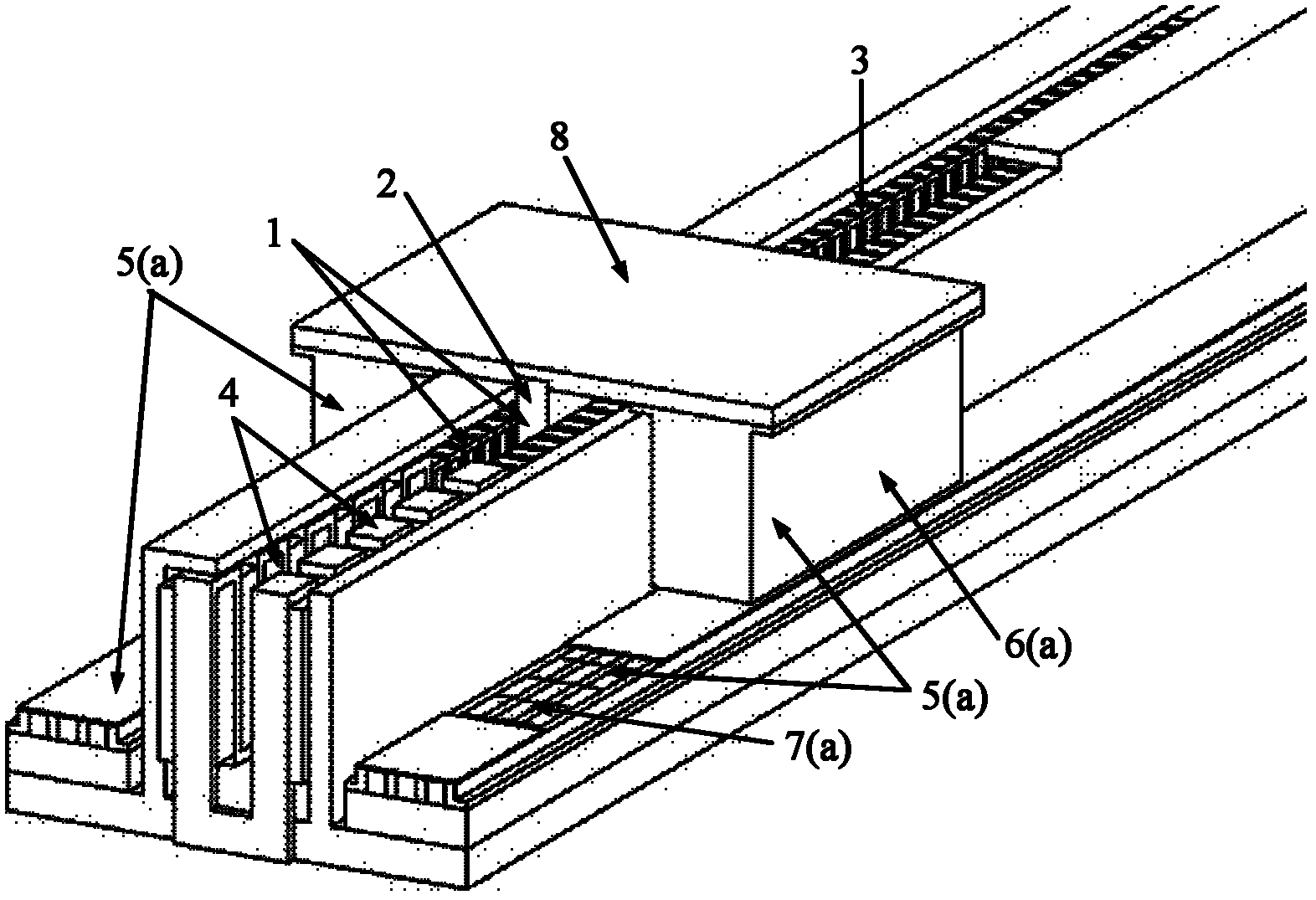
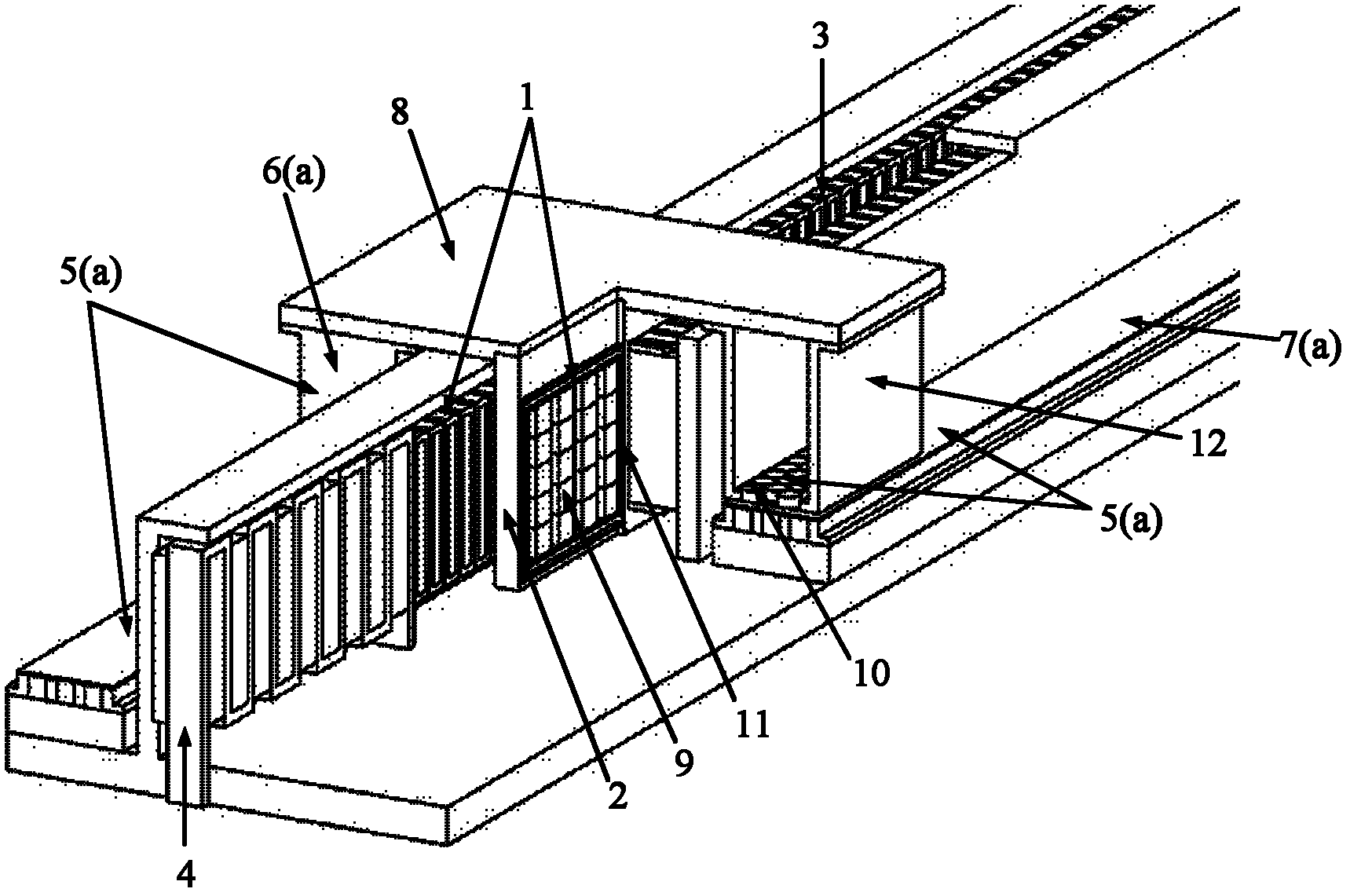
[0031] The overall structure of this embodiment is basically the same as that of Embodiment 1, consisting of a double-sided high-temperature superconducting linear synchronous motor (1), a high-temperature superconducting magnetic levitation subsystem (5 (a)) and a split-type pulse using YBCO high-temperature superconducting coil magnets Coil magnetizing device (4), the only difference is: the split type pulse coil magnetizing device (4) is composed of two parallel S-shaped winding pulse coil groups using YBCO strips. Each S-shaped pulse charging coil can generate a pair of poles with opposite polarity pulse magnetic field, and the span of each S-shaped pulse charging coil is equal to one of the high-temperature superconducting bulk magnet array (9) in (1). The length of the poles.
[0032] When magnetizing, move the secondary mover (2) installed with the high-temperature superconducting block magnet array (9) in (1) to the split type pulse coil magnetizing device (4), so that...
PUM
 Abstract
Description
Claims
Application Information
 - R&D
- Intellectual Property
- Life Sciences
- Materials
- Tech Scout
- Unparalleled Data Quality
- Higher Quality Content
- 60% Fewer Hallucinations
Browse by: Latest US Patents, China's latest patents, Technical Efficacy Thesaurus, Application Domain, Technology Topic, Popular Technical Reports.
© 2025 PatSnap. All rights reserved.Legal|Privacy policy|Modern Slavery Act Transparency Statement|Sitemap|About US| Contact US: help@patsnap.com


