
Intramedullary nail device

A bone marrow and internal nail technology, applied in the field of orthopaedic internal fixation devices, can solve the problems of pain, low cut-out resistance of lag screws, easy loosening, etc., and achieve the effects of increasing effective blood supply, stable and reliable fixation, and preventing rotation.

Inactive Publication Date: 2011-11-09
CHANGZHOU ORTHMED MEDICAL INSTR
View PDF3 Cites 5 Cited by
  • Summary
  • Abstract
  • Description
  • Claims
  • Application Information

AI Technical Summary

Problems solved by technology

Usually, the hole of the lag screw installed on the intramedullary nail is designed as a circle. After the circular pull hole is equipped with a cylindrical lag screw, the garbage screw is easy to rotate, which will bring discomfort and even pain to the injured.
In surgery for fracture treatment, intramedullary nails are usually used to fix the fracture site. Intramedullary nails need lag screws to fix them on the bones of the human body. When the human body is active, the movement tendency of the femoral head is to break away from the tension. The tightening of the screw, that is, the lag screw tends to withdraw from the femoral head. The threaded structure lag screw has a small anti-cutting force, and the pressure on the bone is small during the process of penetrating into the bone. Therefore, the threaded structure Lag screws tend to loosen after installation

Method used


Image

  • Intramedullary nail device
  • Intramedullary nail device
  • Intramedullary nail device

Examples


Embodiment 1

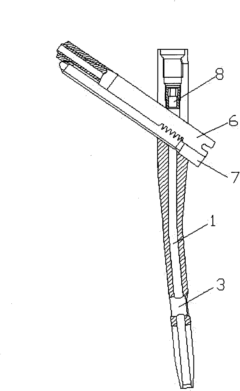
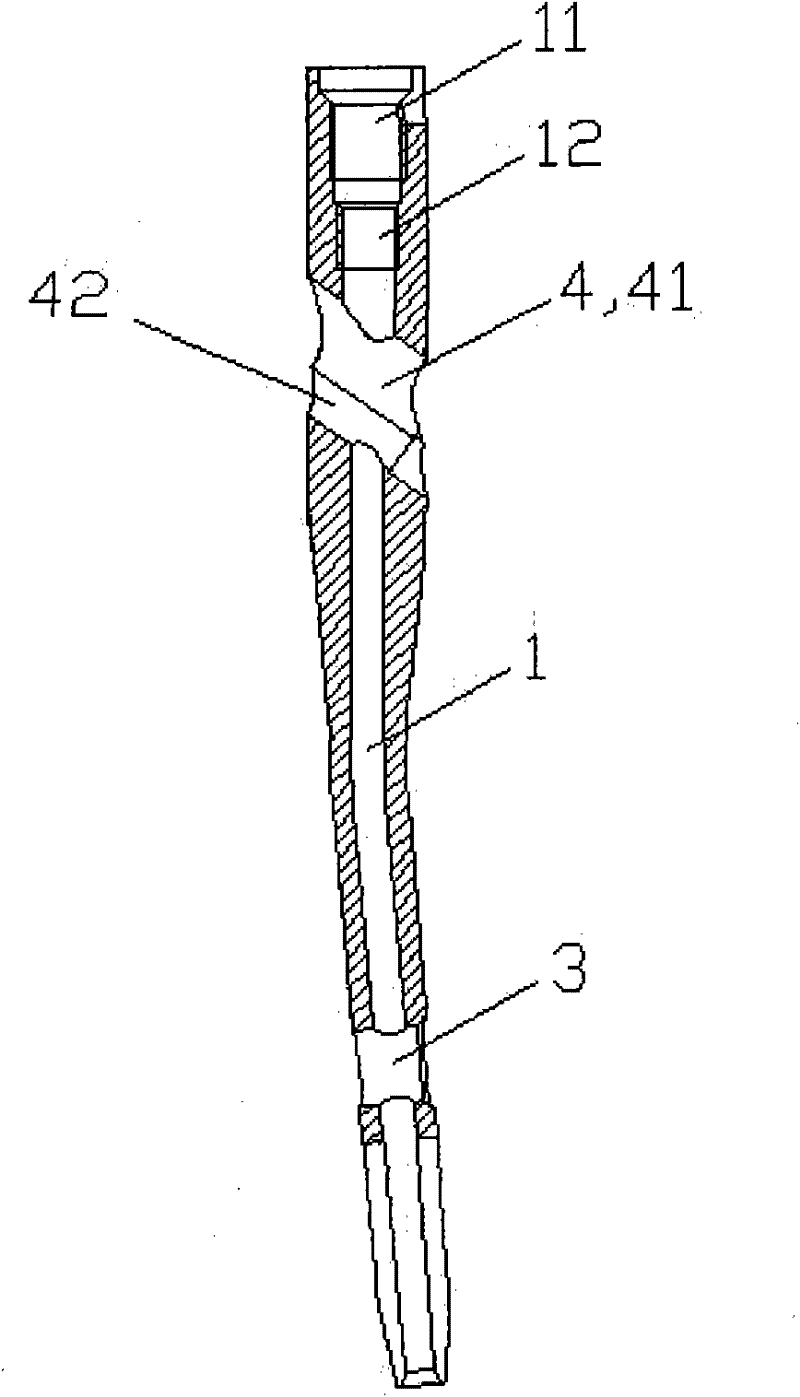
[0036] See Figure 1 to Figure 12 , the intramedullary nail device in this embodiment includes an intramedullary nail and a lag screw.

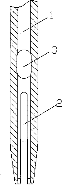
[0037] The distal end and the proximal end of the intramedullary nail are not on the same straight line, and a long through hole 1 is arranged in the axial direction. For connecting caps. The distal end of the intramedullary nail is provided with a long groove 2 and a locking hole 3 in sequence, and the long groove 2 divides the end of the distal end of the intramedullary nail into two symmetrical pieces. The proximal end of the intramedullary nail is provided with an oblique tension hole 4, the tension hole 4 is divided into a large circular hole 41 and a small circular hole 42, the axes of the large circular hole 41 and the small circular hole 42 are parallel, and the large circular hole 41 and the small circular hole 42 Partially overlapping, the diameter of the upper end of the small circular hole 42 is smaller than the diameter of the ...


PUM


Abstract

The invention discloses an intramedullary nail device, which comprises an intramedullary nail device and a lag screw, wherein the far end and near end of the intramedullary nail are not in the same straight line, the intramedullary nail has a long through hole in axial direction, and the near end of the intramedullary nail has an oblique pull hole; when used, the lag screw cooperates with the pull force of an intramedullary nail rod, the lag screw comprises a threaded lag screw and a pressurizing and anti-rotation screw, which are matched with each other; the front end of the threaded lag screw is provided with external threads; an arc-shaped groove is formed on the side face of the threaded lag screw; the rear end of the arc-shaped groove is provided with a plurality of racks which are vertical to the arc-shaped groove and are uniformly spaced; a positioning groove is formed on the tail end of the threaded lag screw; the radian measure of the surface of the pressurizing and anti-rotation screw is the same as that of the arc-shaped groove of the threaded lag screw; the pressurizing and anti-rotation screw consists of a screw positioned on at a front end and a cylinder positioned at the rear end; the diameter of the cylinder is a little bit greater than that of the screw; and the threads on the screw are connected with the jack threads of the threaded lag screw. The intramedullary nail device has a simple structure and can effectively prevent the lag screw from rotating, and after being fixed, the lag screw is stable and reliable.

Description

technical field [0001] The invention relates to an orthopedic internal fixation device, in particular to an intramedullary nailing device. Background technique [0002] When the bones of the human body are fractured, intramedullary nails are usually used to connect the broken bones. Intramedullary nails generally refer to long steel nails placed in the bone marrow cavity. For example, for the femur and tibia of the lower limbs, after opening a wound at one end of the bone and inserting the intramedullary nail, a lag screw and a fixed nail are respectively installed at the proximal and distal ends of the intramedullary nail to prevent the rotation and shortening of the bone. Usually, the hole of the lag screw installed on the intramedullary nail is designed to be circular. After the circular lag hole is equipped with a cylindrical lag screw, the garbage screw is easy to rotate, which brings discomfort and even pain to the injured. In surgery for fracture treatment, intramedu...

Claims


Application Information

Patent Timeline
Patent Type & Authority Applications(China)
IPC IPC(8): A61B17/72A61B17/86
Inventor 蔡勇于圣泰
Owner CHANGZHOU ORTHMED MEDICAL INSTR
Learn More