Flying disk engine

An engine and duct technology, applied in aircraft control, aircraft parts, aircraft, etc., can solve problems such as inability to achieve balance

Inactive Publication Date: 2011-11-09
鄂雨松
View PDF0 Cites 5 Cited by
  • Summary
  • Abstract
  • Description
  • Claims
  • Application Information

AI Technical Summary

Problems solved by technology

And it is completely different from all the aircraft engines that humans currently have. It is a brand new engine. It is a flying saucer engine. The center of this engine is designed as an empty cylinder. At present, the center of all jet engines in the world is a main shaft. Due to the processing technology Due to technical reasons such as materials and materials, resonance will occur at extremely high speeds, and balance cannot be achieved. Now, the diameter of the main shaft is increased to have a hollow structure with a certain wall thickness. The upper part is small and the lower part is large, which solves the problem of engine shaft resonance at extremely high speeds. Because The high-speed air flow around the hollow main shaft is also a downward spiral structure, and the force direction is uniform, so that the main shaft itself achieves dynamic stability without resonance. The modified compressor impeller mechanism subverts all current compressor impeller designs in the world, and all current compressor turbine designs They all make the gas go outward or the vertical parallel axis to compress the gas backwards, and we designed this brand new gas collecting turbine, the new gas collecting impeller makes all the vertical axis of the airflow point to the center of the turbine, forming a downward spiral rotating airflow, and finally The gas-collecting turbine presses all the gas into the downward-swirling inner spiral duct. The inner duct path is a plurality of independent and separated spiral tubular structures, which spiral downward. Each tubular spiral is a structure with a large upper space, a narrow middle part, and a wide bottom part. The oil supply point and igniter are set in the middle space due to the increase of air pressure, and the bottom turbine is a brand-new rotary tail thruster turbine, and the exhaust direction is perpendicular to the main shaft

Method used


Image

  • Flying disk engine
  • Flying disk engine
  • Flying disk engine

Examples


Embodiment Construction

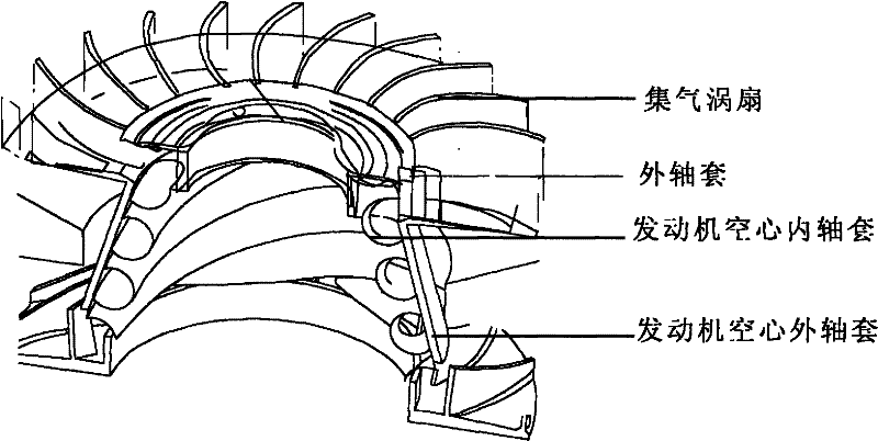
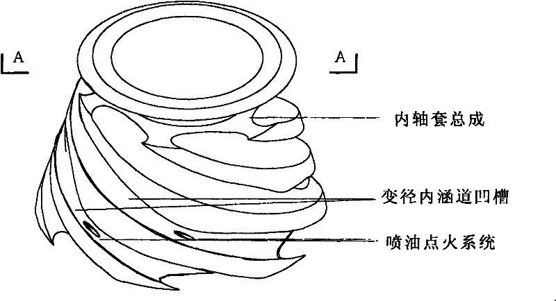
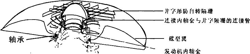
[0014]When the engine is ignited and running, the turbojet engine system is first started. Due to the rotation of the air-gathering turbofan on the top, a large amount of air is pressed into the inner channel, and multiple downward-swirling inner channels and the air-gathering turbofan form the basic structure of the jet engine. Several fuel injection ignition systems inject fuel to ignite, and the engine starts. Since the exhaust direction of the tail turbine is designed to be tangent to the bottom circle of the central shaft sleeve, the flying saucer does not rely entirely on the tail thrust to rise, but spins at high speed. With the increase of fuel injection, the thrust of the bottom turbine increases, and the speed gradually increases. The rotational speed of the turbofan at the top increases year-on-year, so that the compressed air of the air-gathering turbofan also increases, and it rotates faster and faster. A large amount of air is pressed into the exhaust duct from th...


PUM


Abstract

The invention relates to a novel aerospace plane which is conceived on the basis of thought on defense of the galaxy, and belongs to the technical field of aircraft engines. A flying disk engine disclosed by the invention integrates top three of the existing engine technologies of human beings into one, and is an epoch-making aerospace plane. A jet engine and a scramjet direct jet engine have a common feature, i.e., a detonation problem, and however, the flying disk engine disclosed by the invention solves the detonation problem tactfully and can fly and hover at very high speed. The engine is originated from a kite; all aircrafts invented by human beings are based on the imitation of birds which run hard towards the wind with two large wings; from an original propeller to a ramjet engine, all aircrafts made by human beings have wings. The kite is invented in China a long time ago, and flies based on the principle of being blown by the wind, which is completely different from the birds. The basic flying principle of a flying disk is specifically as follows: imagining that a person carrying two wings stands still, a fan is installed in front of the person, and the person is blown by the wind provided by the fan to fly, after the person leaves the ground, no relative motion is generated, another person carrying two wings stands in opposition to the person and is blown by the wind provided by another fan, the two persons are joined together hand in hand, and if people are joined together to form a circle, wind blows towards all directions from the centre, so that the flying disk can fly.

Description

technical field [0001] The invention belongs to an engine used in the field of novel aerospace technology. The saucer-shaped aircraft has always been a dream of human beings. No one has successfully developed it yet, but its natural shape has excellent aerodynamic characteristics and perfect radar invisibility, and it will surely become the ultimate ideal aircraft for human beings. [0002] The reason why humans can’t manufacture saucer-shaped aircraft is that the first reason is that humans have imagined it too complicated, thinking that it has anti-gravity capabilities, eddy currents, and so on. Too many technologies may really exist, but Its original original design must be the power form that our current aircraft can realize; the aerodynamic form. Second, we usually use the conventional propeller dynamic system to drive the disc. Due to the limitation of power, it is difficult to create a real flying saucer. At the beginning of the design of this engine, it was not envisa...

Claims


Application Information

Patent Timeline
Patent Type & Authority Applications(China)
IPC IPC(8): B64C39/06B64D27/10B64C23/00
Inventor 鄂雨松
Owner 鄂雨松
Why Eureka
Try Eureka