
Process liquid feed mechanism

A technology for processing liquids and supply pipes, which is applied in thin material processing, liquid distribution, liquid injection devices, etc. It can solve the problems of time and manpower, problems that are not recorded, and cannot be solved, and achieve the effect of suppressing liquid residues

Active Publication Date: 2011-11-09
TOKYO ELECTRON LTD
View PDF4 Cites 1 Cited by
  • Summary
  • Abstract
  • Description
  • Claims
  • Application Information

AI Technical Summary

Problems solved by technology

The amount of lift-up will also vary depending on the experience and skills of the operator, and sometimes the treatment liquid will remain.
[0010] Moreover, the shape of the liquid storage bottle 101 is various, and sometimes the position adjustment of the processing liquid supply pipe 106 must be performed as described above every time the liquid storage bottle 101 is replaced, which takes time and manpower.
In Patent Document 1, an example of the above-mentioned processing liquid supply mechanism is described, but there is no description about the above-mentioned problem, and the problem cannot be solved.
In addition, in Patent Document 2, the structure of the operation panel cover is described. This operation panel cover is used for gasoline tanks, and has little relevance to the present invention, and cannot solve the above-mentioned problems.

Method used


Image

  • Process liquid feed mechanism
  • Process liquid feed mechanism
  • Process liquid feed mechanism

Examples


Embodiment Construction

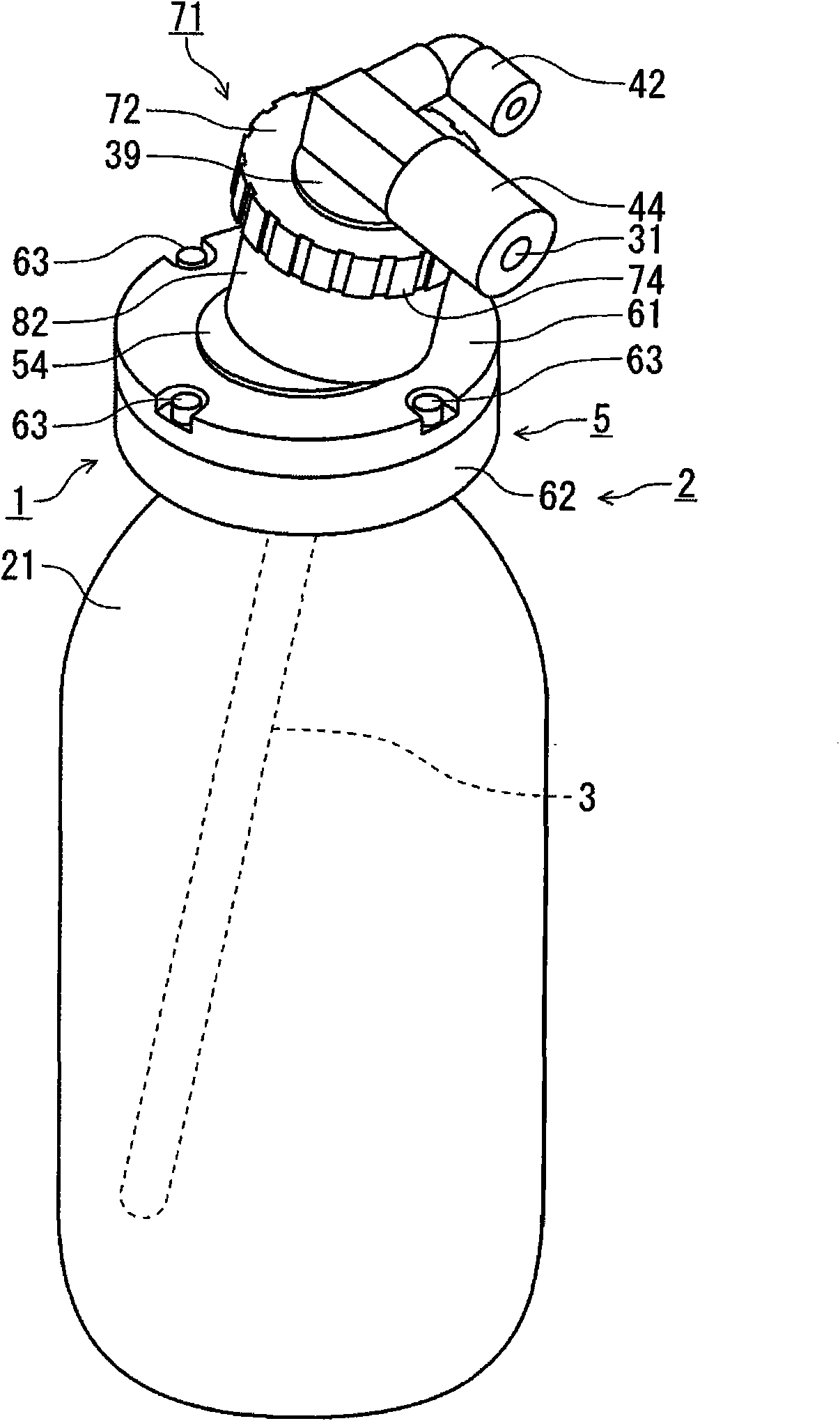
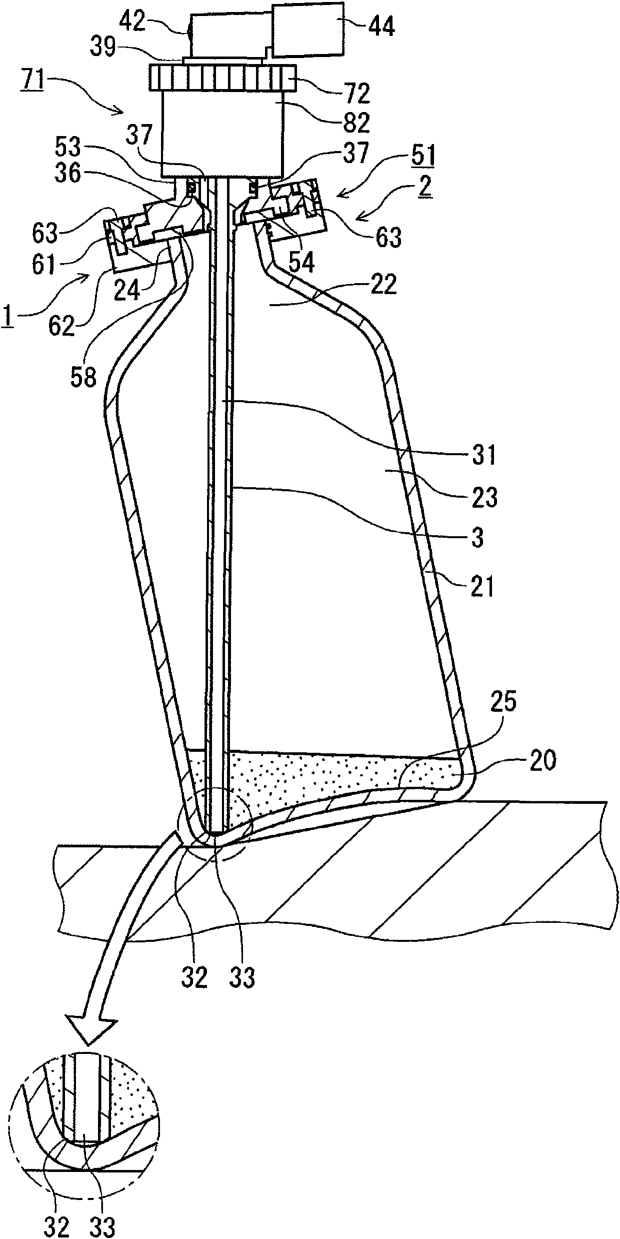
[0035] refer to figure 1 the stereogram and figure 2 The longitudinal cross-sectional side view of the present invention will describe a pressurized resist supply container 2 having a resist supply mechanism 1 as an embodiment of the present invention. The pressurized resist supply container 2 is composed of a resist supply mechanism 1 and a liquid storage bottle 21 as a container body, and the resist supply mechanism 1 is configured to be detachably attached to the liquid storage bottle 21 .

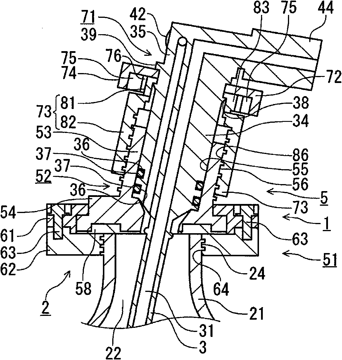
[0036] The resist supply mechanism 1 includes a resist supply pipe 3 and a bottle cap 5 as a processing liquid supply pipe. The liquid storage bottle 21 stores the resist 20 as a processing liquid. The resist supply pipe 3 supplies the above-described resist 20 from the liquid reservoir 21 to the external wafer. The bottle cap 5 has a function of adjusting the height position so that the lower end of the resist supply pipe 3 contacts the bottom of the liquid storage bottle 21 and t...


PUM


Abstract

The invention provides a process liquid feed mechanism capable of preventing residual of the process liquid on a vessel body. The process liquid feed mechanism includes a fixed cylinder projecting upwards from a cover part to the vessel body with a thread around a peripheral surface, a movable cylinder provided coaxially with the fixed cylinder and disposed on the inner side or the outer side of the fixed cylinder, a process liquid feed tube and an operating rotator. The process liquid feed tube is fixed in an axial position relative to the movable cylinder and passes through the lid and a cylinder including the fixed cylinder and the movable cylinder to be axially movable relative to the cylinder. The operating rotator includes an annular portion provided coaxially with the movable cylinder. An engaging portion and an engaged portion, which are provided in the movable cylinder and the annular portion respectively, rotate the movable cylinder through engagement therebetween with rotation of the operating rotator and release the engagement as a torque on the movable cylinder increases. Therefore, the lower end of the process liquid feed tube is abutted against the bottom of vessel body to be fixed.

Description

technical field [0001] The present invention relates to a processing liquid supply mechanism used in a container body that stores a processing liquid such as a resist and pressurizes the processing liquid with a pressurizing gas. Background technique [0002] In the photolithography process of the manufacturing process of a semiconductor device, various processing liquids, such as a resist, are supplied to a board|substrate, for example, a semiconductor wafer (henceforth a wafer). [0003] like Figure 15 As shown, a resist supply mechanism 102 that can be attached to and detached from the liquid storage bottle 101 is provided on the liquid storage bottle 101 in which the resist 110 is stored. The resist supply mechanism 102 has a cap 104 that closes the opening 103 of the liquid storage bottle 101, and a pressurized gas such as nitrogen (N 2 ) into the liquid storage bottle 101. Accordingly, the resist 110 flows into the processing liquid supply pipe 106 whose lower end i...

Claims


Application Information

Patent Timeline
Patent Type & Authority Applications(China)
IPC IPC(8): B65D83/16B65D85/00
CPCB05B15/005B05B9/03Y10T137/314Y10T137/8593Y10T137/86332B05B15/30B05C11/1002G03F7/2041G03F7/70691H01L21/0274
Inventor 中岛常长白石俊介竹尾俊英
Owner TOKYO ELECTRON LTD
Learn More