
Power conversion device

A technology of power conversion device and output current, applied in the direction of output power conversion device, electrical components, etc., can solve problems such as semiconductor component damage, and achieve the effect of preventing damage

Active Publication Date: 2015-04-22
FUJI ELECTRIC CO LTD
View PDF2 Cites 0 Cited by
  • Summary
  • Abstract
  • Description
  • Claims
  • Application Information

AI Technical Summary

Problems solved by technology

However, the background art is aimed at the application of gradually controlling the output current by the PWM switch, and it is not suitable for the case where the freewheeling diode undergoes a sharp reverse recovery only once, and the semiconductor element is destroyed.

Method used


Image

  • Power conversion device
  • Power conversion device
  • Power conversion device

Examples


Embodiment approach 1

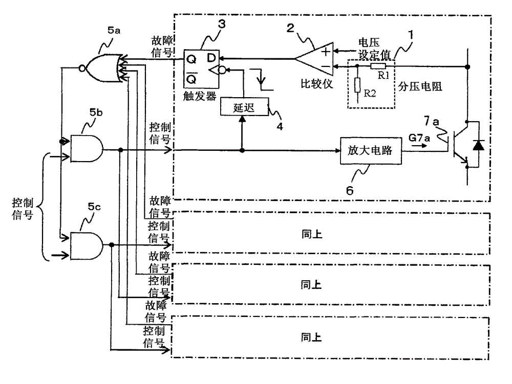
[0044] figure 1 The first embodiment of the present invention is shown. The operation waveform diagram of each part and the background art are similarly shown in Figure 4 . is in image 3 A configuration in which a protection circuit is provided in each of the IGBTs 7a to 7d.

[0045] first of all, yes Figure 4 Be explained.

[0046] Compared with the normal output voltage Vo, at point A when the output current Io is lagging behind the phase, since the current flows through the IGBT7a, 7d that is turned off, after a predetermined time after the gate signal G7a, G7d is turned off (for preventing up and down The voltage Ed of the DC capacitor 7e is added to the voltages of the IGBTs 7a and 7d at the point A' at any point during the dead time of the short circuit of the arm. The power supply is hundreds of V or more.

[0047]Due to an abnormality of the induction heating load, etc., the current flows through the freewheeling diodes of the IGBTs 7a and 7d that are turned ...

Embodiment approach 2

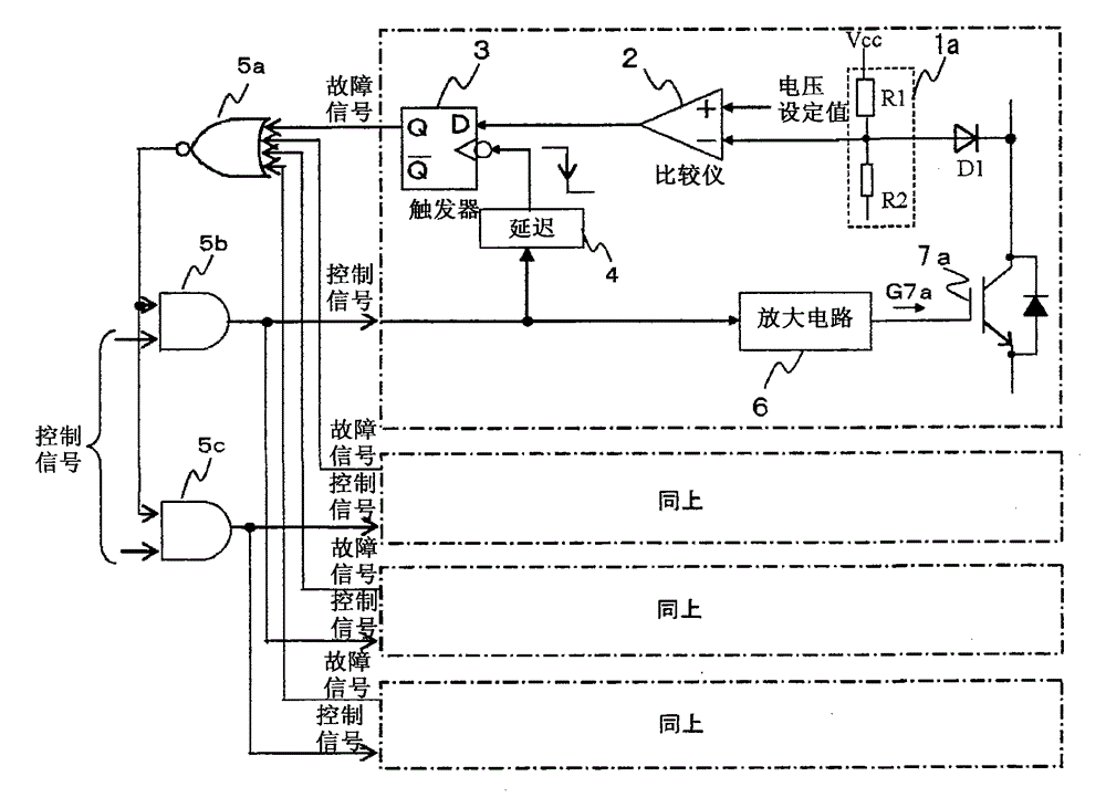
[0057] figure 2 The second embodiment of the present invention is shown.

[0058] The difference from the first embodiment lies in the difference in the circuit for detecting the voltage between the main terminals of the IGBT7a. In this configuration, a series circuit of resistors R1 and R2 is connected between Vcc of the control circuit power supply and the emitter of IGBT7a, and a diode D1 is connected between the series connection point and the collector of IGBT7a. By using the comparator 2 to compare the voltage at the series connection point of the resistor series circuit with the set voltage value, protection can be performed in the same manner as in the first embodiment. Other operations are the same as in Embodiment 1. In this configuration, the voltage applied to the resistors is lower than that of the first embodiment, so the voltage dividing resistors can be miniaturized.

[0059] In addition, the effective use of this proposal is that after the control signal i...


PUM


Abstract

In a resonance-type induction heating device performing operation via delaying motions, when a load abnormity, etc. becomes an advanced motion, a diode of an inverter circuit is made to perform reverse recovery and be destroyed. The invention provides a power conversion device, which is provided with a voltage detecting circuit detecting voltages among main terminals of a semiconductor element, a voltage comparing circuit comparing a voltage setting value and a voltage detecting value, when the semiconductor element is cut off, the voltage setting value and the voltage detecting value are compared, when the voltage setting value is larger, the semiconductor element is in a serial connection, and the semiconductor element is not turned on to construct upper-lower relative arms.

Description

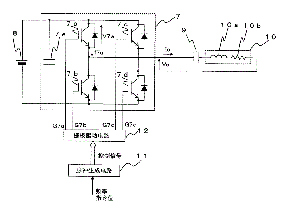
technical field [0001] The present invention relates to a protection circuit for a semiconductor element of a power conversion device, in which a resonant capacitor and an induction heating load are connected to an output, and the output current is operated with a lagging phase relative to the output voltage. Background technique [0002] image 3 represents a circuit diagram for explaining the background art, Figure 4 Indicates its operation waveform diagram. first of all, yes image 3 The circuit diagram is shown for illustration. [0003] The power converter 7 having a DC power supply 8 as a DC input is a single-phase rectangular wave output voltage inverter composed of a DC capacitor 7e and IGBTs 7a to 7d connected in antiparallel to diodes. An induction heating load 10 formed of a resonance capacitor 9, an inductance component 10a, and a resistance component 10b is connected to the output thereof, and a resonance circuit is constituted as a whole. Here, a frequency ...

Claims


Application Information

Patent Timeline
Patent Type & Authority Patents(China)
IPC IPC(8): H02M1/32
Inventor 三浦敏荣仓田严
Owner FUJI ELECTRIC CO LTD
Learn More