Heat radiating device

A technology of heat dissipation device and radiator, applied in indirect heat exchangers, heat exchange equipment, lighting and heating equipment, etc., can solve problems such as unfavorable heat transfer, exposure of heat pipes to the outside world, and reduction of heat dissipation area of ​​heat dissipation devices.

Inactive Publication Date: 2011-11-09
FU ZHUN PRECISION IND SHENZHEN +1
View PDF3 Cites 4 Cited by
  • Summary
  • Abstract
  • Description
  • Claims
  • Application Information

AI Technical Summary

Problems solved by technology

[0003] The heat dissipation device usually includes a heat dissipation fin set and a heat pipe thermally connecting the heat dissipation fin set to the electronic component. The oblique shape, however, the inclined and bent part of the heat pipe is difficult to be closely combined with the heat dissipation fin group, which is not conducive to the transfer of heat. The fins are removed, which will not only reduce the heat dissipation area of ​​the heat sink, but also expose the bent part of the heat pipe to the outside, thus affecting the appearance of the heat sink

Method used


Image

  • Heat radiating device
  • Heat radiating device
  • Heat radiating device

Examples


Embodiment Construction

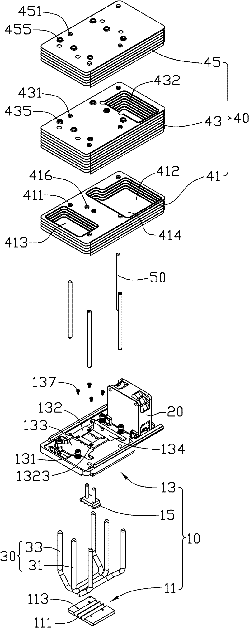
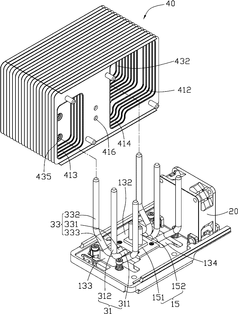
[0050] figure 1 and figure 2 Shown is the heat dissipation device in the first embodiment of the present invention, which is used to dissipate heat from a heat-generating electronic component (not shown) such as a central processing unit. The heat dissipation device includes a base 10, a fan 20 placed on the base 10, a heat pipe assembly 30 combined with the base 10, a radiator 40 combined with the heat pipe assembly 30, and a radiator 40 inserted through the radiator. Several conductive rods 50 in 40.

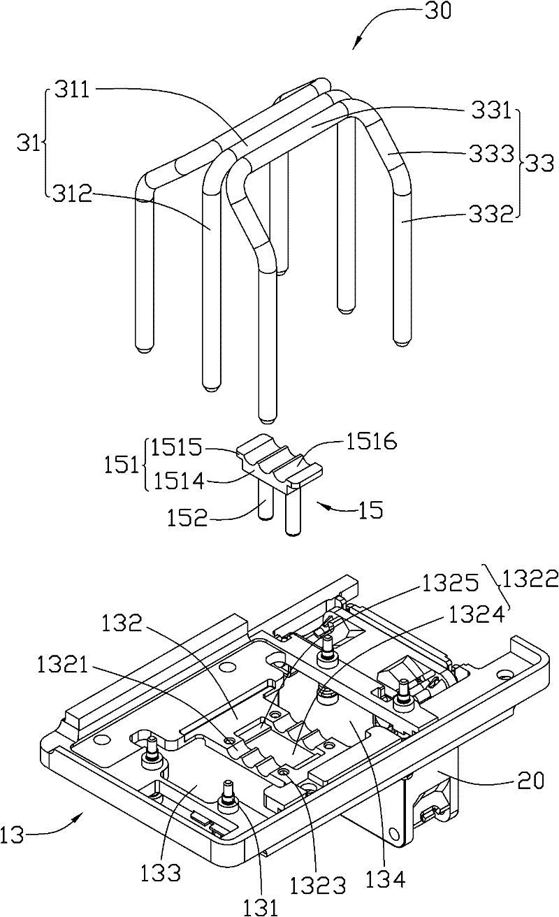
[0051] The base 10 includes a substrate 11 , a fixing frame 13 and a heat transfer element 15 combined on the substrate 11 .

[0052] The substrate 11 is rectangular and made of materials with good thermal conductivity such as copper and aluminum. The lower surface of the substrate 11 is used for thermal contact with the heat-generating electronic components, and the middle of the upper surface is provided with a plurality of parallel spaced semicircular receiving grooves ...


PUM


Abstract

The invention relates to a heat radiating device. The heat radiating device comprises a heat radiator and a heat pipe, wherein the heat radiator comprises a plurality of first heat radiating fins and second heat radiating fins which are stacked and arranged up and down; the heat pipe comprises an evaporation section, a condensation section and a connecting section connecting the evaporation section with the condensation section; the evaporation section is used for thermally connecting with a heat source; the condensation section is thermally combined onto the second heat radiating fins; accommodation grooves are arranged on the first heat radiating fins; the connecting section is formed by the extension of the evaporation section slantingly facing to the first heat radiating fins; and the connecting section is accommodated in the accommodation grooves of the first heat radiating fins and non-thermally connected with the first heat radiating fins. The heat radiating device also comprises a heat transfer member, wherein the heat transfer member is thermally combined onto the first heat radiating fins and used for thermally connecting the heat source with the first heat radiating fins. According to the heat radiating device, the heat radiator arranged at a corresponding position of the slanted and bent connecting-section of the heat pipe is fully utilized, and therefore the heat radiating area of the heat radiating device is increased.

Description

technical field [0001] The present invention relates to a heat dissipation device, in particular to a heat dissipation device used for heat dissipation of heat-generating electronic components. Background technique [0002] With the rapid development of the electronic industry, the high-speed, high-frequency and integration of electronic components (such as central processing units) make the calorific value increase dramatically. In order to efficiently remove the heat generated by electronic components in a limited space, the industry usually uses Install a cooling device on the electronic component. [0003] The heat dissipation device usually includes a heat dissipation fin set and a heat pipe thermally connecting the heat dissipation fin set to the electronic component. The oblique shape, however, the inclined and bent part of the heat pipe is difficult to be closely combined with the heat dissipation fin group, which is not conducive to the transfer of heat. The fins ...

Claims


Application Information

Patent Timeline
Patent Type & Authority Applications(China)
IPC IPC(8): H05K7/20G06F1/20
CPCH01L23/427H01L23/3672H01L23/467H01L2924/0002F28D15/0275F28F1/32H01L2924/00
Inventor 李伟吴宜强
Owner FU ZHUN PRECISION IND SHENZHEN
Why Eureka
Try Eureka