Eureka AIR delivers breakthrough ideas for toughest innovation challenges, trusted by R&D personnel around the world.

Methods for selecting and controlling devices

A technology for equipment and target selection, applied in access restrictions, instruments, light sources, etc., can solve problems such as long delay and unsatisfactory user experience, and achieve the effect of reducing delay, simplifying processing complexity, and reducing electromagnetic radiation

Active Publication Date: 2011-11-09
SIGNIFY HLDG BV
View PDF7 Cites 22 Cited by
  • Summary
  • Abstract
  • Description
  • Claims
  • Application Information

AI Technical Summary

Problems solved by technology

These deficiencies lead to longer delays before target devices are selected and controlled by the wireless controller and result in an unsatisfactory user experience

Method used

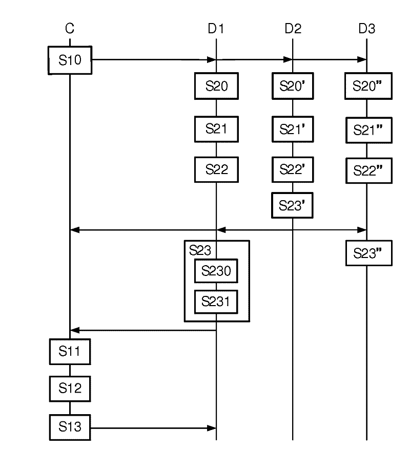

Image

  • Methods for selecting and controlling devices
  • Methods for selecting and controlling devices
  • Methods for selecting and controlling devices

Examples


Embodiment 1

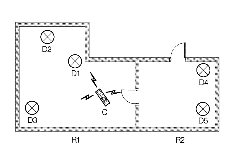
[0018] figure 1 The topology of a lighting area based on a wireless control network is shown. The lighting area is an indoor environment and includes two adjacent rooms R1 and R2. Luminaires D1 to D3 are installed in room R1 and D4 and D5 are installed in room R2. The wireless controller C sends a control signal to each lamp by unicast or multicast based on the unique identifier of each lamp to control its lighting functions, such as on / off, brightness, color, focus and rotation. The commissioning of the luminaires is done, which means the system knows where each luminaire is. Commissioning methods are well known to those skilled in the art and further details will not be given herein.

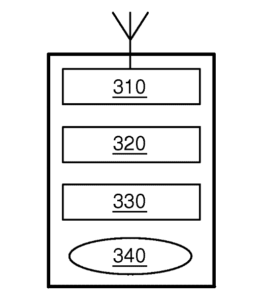
[0019] Such as figure 2 As shown, each light fixture includes a lighting component 210, using a wireless protocol (such as ZigBee TM ), the wireless communication module 220 , the processor 230 , the memory 240 and the power supply 250 . The wireless communication module 220 uses ZigBee...

Embodiment 2

[0064] Such as Figure 6 As shown, the transmit antenna of wireless controller C is directional, such as a directional antenna with beamforming capability. This antenna has relatively strong transmission power in the range of angle A (such as the direction pointed by wireless controller C), and has relatively weak transmission power in another angle range. Therefore, when the user wants to select the light fixture D2 and control it, the user can point his hand-held wireless controller C to D2. In this way, the azimuth angle θ (which is the angle between the peak emission direction and the direction pointing to D2) between the emission angles of luminaire D2 and wireless controller C is relatively small, while the azimuth angles of luminaires D3 and D1 are relatively large.

[0065] First, the wireless controller C broadcasts a detection message, and the transmission power within the angle A is strong, while the transmission power outside the angle A is weak.

[0066] Subsequ...


PUM


Abstract

A method of selecting and controlling devices based on wireless communication technology. The wireless controller sends a probe message to one or more devices; each device receives the probe message, obtains information in respect of its relative position with respect to the wireless controller, determines a response time to respond according to a first predefined rule, based on its relative position information: detects response signals from other devices before expiration of the response time; decides whether to send or not to send its response signal according to a second predefined rule and the detecting procedure of response signals from other devices; ; the wireless controller receives response signals sent by the devices after the comparison of the relative position information of each device with respect to the wireless controller, and selects the target devices from the devices. Embodiments of the present invention reduce the complexity, delay and energy consumption of the selection for wireless devices, and are especially applicable for wireless lighting systems.

Description

technical field [0001] The invention relates to equipment selection and control, in particular to a method for selecting and controlling equipment based on wireless communication technology. Background technique [0002] In indoor and outdoor environments where people live and work, various kinds of electronic and electrical equipment are used, such as multiple light fixtures located in different locations. The user selects and controls these devices to meet his work and life needs. Currently, people typically use stationary controls, such as control panels mounted on a wall, to control these devices. In this case, if the user wants to control the device, he has to go to the control panel to operate the button or knob corresponding to the device. When the number of devices increases, the control panel becomes more complex as many buttons or knobs correspond to multiple devices, and the user must remember which buttons control which device. Although wireless communication ...

Claims


Application Information

Patent Timeline
Patent Type & Authority Applications(China)
IPC IPC(8): H05B37/02G08C17/02
CPCH04W48/20G08C2201/91G08C2201/71H05B37/0272G08C17/02H05B47/19H05B47/1965H05B47/155
Inventor 冯雷D.杨Z.陈
Owner SIGNIFY HLDG BV
Why Eureka
Eureka Blog
Learn More