Technology for manufacturing hard alloy thin-wall shaft sleeve

A hard alloy and manufacturing process technology, applied in the field of hard alloy thin-walled bushing manufacturing technology, can solve the problems of cost reduction, difficulty in forming thin-walled bushings, and spray welding of bushings, etc., and achieve great economic value , Significant technological advancement and low manufacturing cost

Inactive Publication Date: 2011-11-16
自贡市巨光硬面材料科技有限公司
View PDF8 Cites 10 Cited by
  • Summary
  • Abstract
  • Description
  • Claims
  • Application Information

AI Technical Summary

Problems solved by technology

[0002] At present, the method of powder metallurgy is often used to manufacture cemented carbide sleeves, but due to its technological characteristics, it is difficult to realize the molding of thin-walled sleeves, and thicker sleeves are not conducive to reducing costs; if used inside and outside of ordinary sleeves The method of surface spray welding reduces the manufacturing cost of the cemented carbide bushing, but due to its technological limitations, spray welding cannot be realized for the inner surface of the bushing with a smaller inner diameter

Method used


Image

  • Technology for manufacturing hard alloy thin-wall shaft sleeve
  • Technology for manufacturing hard alloy thin-wall shaft sleeve
  • Technology for manufacturing hard alloy thin-wall shaft sleeve

Examples


Embodiment Construction

[0015] All features disclosed in this specification, or steps in all methods or processes disclosed, may be combined in any manner, except for mutually exclusive features and / or steps.

[0016] Any feature disclosed in this specification (including any appended claims, abstract and drawings), unless expressly stated otherwise, may be replaced by alternative features which are equivalent or serve a similar purpose. That is, unless expressly stated otherwise, each feature is one example only of a series of equivalent or similar features.

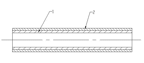
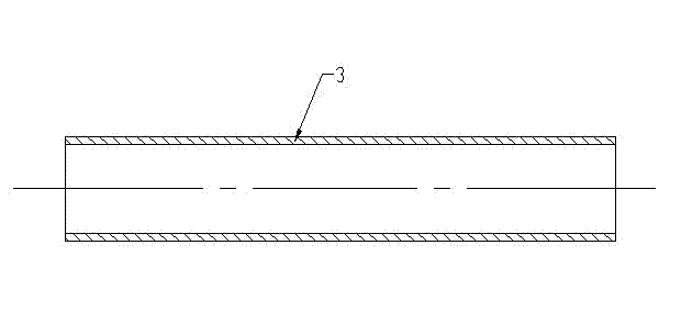
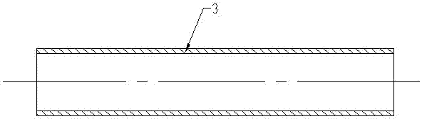
[0017] Such as figure 1 and figure 2 Shown, a kind of cemented carbide thin-walled axle sleeve manufacturing process of the present invention comprises the following operations: A, parison processing: adopt round steel pipe or tapered steel pipe as axle sleeve parison 1, trim its outer circle size; B, spray Welding: Spray-weld hard alloy materials on the outer surface of the shaft sleeve blank to form a uniform spray-welding layer 2; C, out...


PUM


Abstract

The invention relates to a technology for manufacturing a hard alloy thin-wall shaft sleeve, which comprises the following processes of: A, parison machining: taking a circular steel tube or a taper steel tube as a shaft sleeve parison and trimming a size of an excircle; B, spray-welding: spray-welding a hard alloy material on the external surface of the shaft sleeve parison to form an even spray-welded layer; C, external surface machining: turning or grinding a size of an excircle of the spray-welded layer; and D, internal surface machining: cutting to remove the shaft sleeve parison by using a turning or grinding method, so as to form the hard alloy shaft sleeve. The technology for manufacturing the hard alloy thin-wall shaft sleeve, provided by the invention, is a manufacturing method which comprises the following steps of: firstly spray-welding the hard alloy material on the external surface of the shaft sleeve parison and then cutting to remove the shaft sleeve parison, so as to form the hard alloy shaft sleeve, so that the molding of small-bore thin-wall hard alloy shaft sleeves is realized, and the technical difficult problem that the small-bore thin-wall hard alloy shaft sleeves are difficult to be manufactured through a powder metallurgy molding and double-surface spray-welding method currently is solved.

Description

technical field [0001] The invention relates to a manufacturing process of a shaft sleeve, in particular to a manufacturing process of a hard alloy thin-walled shaft sleeve. Background technique [0002] At present, the method of powder metallurgy is often used to manufacture cemented carbide sleeves, but due to its technological characteristics, it is difficult to realize the molding of thin-walled sleeves, and thicker sleeves are not conducive to reducing costs; if used inside and outside of ordinary sleeves Although the surface spray welding method reduces the manufacturing cost of the cemented carbide bushing, due to its technological limitations, spray welding cannot be realized on the inner surface of the bushing with a smaller inner diameter. Contents of the invention [0003] The technical problem to be solved by the present invention is to provide a process method capable of manufacturing small-caliber hard alloy thin-walled shaft sleeves. [0004] In order to so...

Claims


Application Information

Patent Timeline
Patent Type & Authority Applications(China)
IPC IPC(8): B23P15/00
Inventor 卢超何平
Owner 自贡市巨光硬面材料科技有限公司
Why Eureka
Try Eureka