Pneumatic flexible swinging joint

A joint and flexible technology, applied in the field of pneumatic flexible swing joints, can solve the problems of difficult control and difficult swing of pneumatic swing joints, and achieve the effect of easy control, good applicability and good flexibility

Inactive Publication Date: 2011-11-16
ZHEJIANG UNIV OF TECH
View PDF8 Cites 5 Cited by
  • Summary
  • Abstract
  • Description
  • Claims
  • Application Information

AI Technical Summary

Problems solved by technology

[0003] The present invention aims to solve the problems of difficult control and difficult swing in existing pneumatic swing joints, and provides a pneumatic flexible swing joint with flexible movements, convenient installation and easy control

Method used


Image

  • Pneumatic flexible swinging joint
  • Pneumatic flexible swinging joint
  • Pneumatic flexible swinging joint

Examples


Embodiment Construction

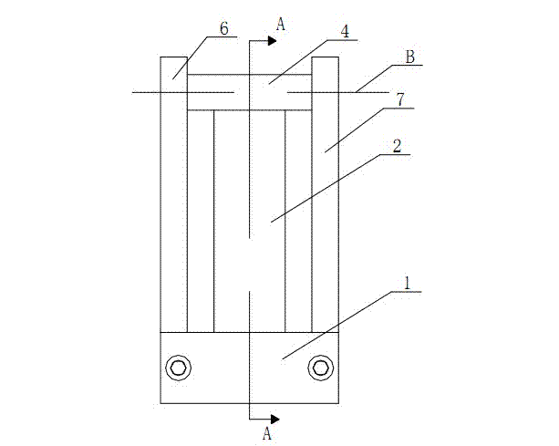
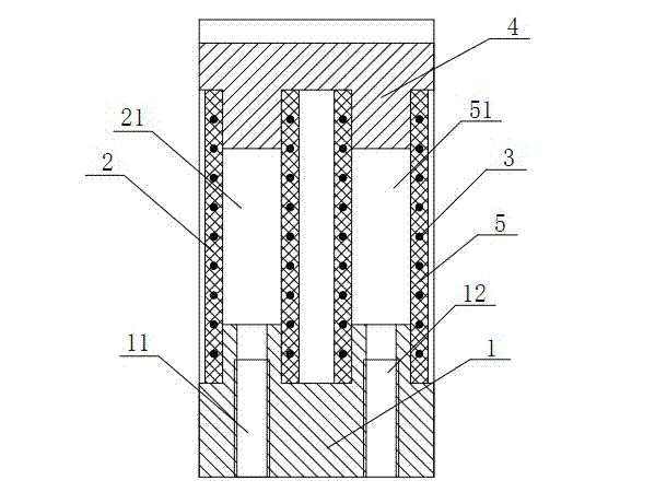
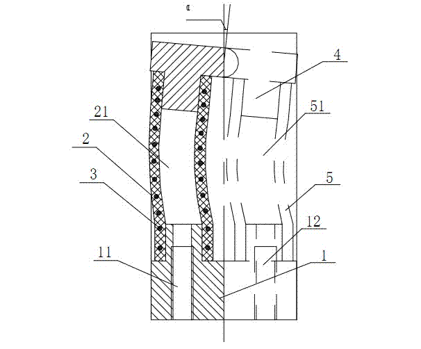
[0014] refer to Figure 1-3 , a pneumatic flexible swing joint, including a base 1 and an end cover 4, a first rubber tube 2 and a second rubber tube 5 arranged in parallel front and back are sealingly connected between the base 1 and the end cover 4, the first rubber tube 2 and the space in the second rubber tube 5 are respectively the first joint inner cavity 21 and the second joint inner cavity 51, and the first threaded hole 11 and the second threaded hole 12 communicating with the atmosphere are opened on the base 1, and the The first threaded hole 11 communicates with the first joint cavity 21, and the second threaded hole 12 communicates with the second joint cavity 51; both the first rubber tube 2 and the second rubber tube 5 are embedded with a wire 3 ; The base 1 is fixedly connected with a left baffle 6 and a right baffle 7, and the left baffle 6 and the right baffle 7 are hinged with the end cover 4.

[0015] The metal wire 3 is a helical steel wire.

[0016] An ...


PUM


Abstract

The invention relates to a pneumatic flexible swinging joint which comprises a base and an end cover, wherein a first rubber hose and a second rubber hose, which are parallel from front to back, are hermetically connected between the base and the end cover; spaces in the first rubber hose and the second rubber hose are respectively a first internal joint cavity and a second internal joint cavity; a first threaded hole and a second threaded hole which are communicated with atmosphere are formed on the base; the first threaded hole is communicated with the first internal joint cavity; the second threaded hole is communicated with the second internal joint cavity; metal wires are embedded in both of the first rubber hose and second rubber hose; a left baffle and a right baffle are fixedly connected to the base; and the left baffle and the right baffle are hinged with the end cover. The pneumatic flexible swinging joint has the advantages that the structure is simple, the pneumatic flexible swinging joint can be easily miniaturized and can be conveniently assembled, disassembled and maintained, the operation is flexible, and the application value is higher.

Description

technical field [0001] The invention relates to an aerodynamic flexible swing joint. Background technique [0002] With the rapid development of modern robot technology, the traditional gripping mechanism at the end of the robot can no longer meet the tasks of the robot, so the dexterous hand of the humanoid robot has received extensive attention. The robotic dexterous hand, which is based on the human hand, not only completes the flexion movement, but also realizes the swing. Therefore, the design of the swing joint becomes one of the key technologies in the design of the robot dexterous hand. The traditional design idea is based on a purely mechanical structure. The joints of the manipulator are formed in the form of pulleys, steel cables, and chains. The main disadvantage is that an external transmission mechanism is required, and a motor or hydraulic drive is required. The space size is large, the structure is complex, and the power to weight ratio is low. Small, diffi...

Claims


Application Information

Patent Timeline
Patent Type & Authority Applications(China)
IPC IPC(8): B25J17/02
Inventor 张立彬邵铁锋杨庆华鲍官军
Owner ZHEJIANG UNIV OF TECH
Why Eureka
Try Eureka