
Continuous pressurizing oil-injection quenching device

A technology of quenching device and quenching press, which is applied in the direction of quenching device, heat treatment equipment, manufacturing tools, etc., can solve the problems of increasing processing difficulty, large amount of free deformation, and large number of operators, so as to achieve uniform internal stress distribution of the matrix and product The effect of improving flatness and controlling product quality

Inactive Publication Date: 2011-11-16
HEIXUANFENG SAW IND
View PDF2 Cites 8 Cited by
  • Summary
  • Abstract
  • Description
  • Claims
  • Application Information

AI Technical Summary

Problems solved by technology

[0003] In the quenching treatment of the saw blade substrate in the prior art, one piece or several pieces are generally heated at a time, and then single piece or several pieces are quenched together after heating, so the production efficiency is low, and the number of operators is large, and the degree of automation is not high.
At the same time, during the quenching process, the saw blade substrate directly enters the quenching medium, resulting in a large amount of free deformation and poor flatness, which is not conducive to controlling the quality of the workpiece, increases the processing difficulty of subsequent processes, and increases the labor intensity of operators

Method used


Image

  • Continuous pressurizing oil-injection quenching device
  • Continuous pressurizing oil-injection quenching device
  • Continuous pressurizing oil-injection quenching device

Examples


Embodiment Construction

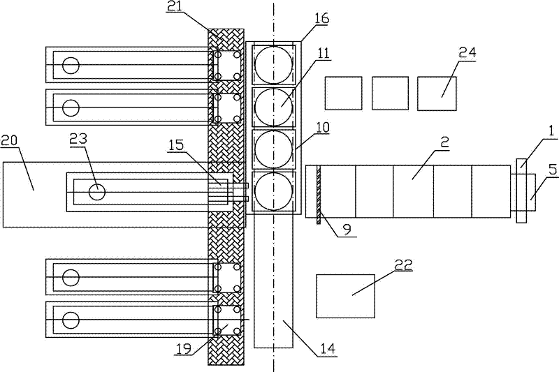
[0018] Such as figure 1 and figure 2 As shown, a continuous pressurized oil injection quenching production device includes an oil tank 20, a heating element 4 is arranged in a roller hearth type continuous heating furnace 2, a feeding device 1 is arranged on one side of the roller hearth type continuous heating furnace 2, and a feeding device 1 is arranged on the other side An oil spray quenching press 10 is arranged on the side, and the oil spray quenching press 10 is placed in the oil tank 16, between the sheet taking manipulator 15 and the roller bottom type continuous heating furnace 2, the oil tank 16 communicates with the oil tank 20 through the oil delivery pipe 17, The retrieving manipulator 19 is located at both sides of the taking sheet manipulator 15 .

[0019] The oil injection quenching press 10 has an upper platen 11 and a lower platen 3, the upper and lower platens have hollow honeycomb fuel injection nozzles 12, the lower platen 3 is fixed, the upper platen 1...


PUM


Abstract

The invention provides a continuous pressurizing oil-injection quenching device, belonging to the field of thermal treatment devices. The continuous pressurizing oil-injection quenching device is mainly used for pressurizing quenching treatment of a saw web substrate. The continuous pressurizing oil-injection quenching device mainly comprises a feeding device, a roller bottom type continuous heating furnace, a saw web taking mechanical arm, an oil-injection quenching press, a discharging mechanical arm, a material discharging transference net belt, an oil groove and the like, wherein the heating furnace is used for heating and insulating the saw web body so as to meet the quenching requirement; and the saw web taking mechanical arm feeds the saw web substrate which reaches the quenching requirement to the oil-injection quenching press for pressing and oil-injection quenching, wherein a quenching medium is delivered to the quenching press and then circularly flows back to the oil groove. The device provided by the invention has the advantages of high production efficiency, even product hardness, less deformation amount, high automation control degree, low energy consumption, good work environment and the like, is beneficial to work piece quality control and is simple to operate; the product after thermal treatment has even hardness and less deformation amount, can be matched with a control system, and a full-automatic control process of thermal treatment processes such as feeding, heating, planishing, quenching, discharging, transferring work pieces and the like can be achieved.

Description

technical field [0001] The invention belongs to the field of heat treatment devices, in particular to a metal plate quenching device. Background technique [0002] In the production of metal materials, especially in the production of steel materials, in order to improve the subsequent processing performance of the product or the use performance of the final product, the product needs to be heat treated during the production process, including annealing, quenching, normalizing, tempering, etc. In the production process of the saw blade base, in order to improve the strength and plasticity of the saw blade base, it is usually necessary to quench and temper the saw blade base. [0003] In the quenching treatment of the saw blade substrate in the prior art, one or several pieces are generally heated at a time, and then single or several pieces are quenched together after heating, so the production efficiency is low, and the number of operators is large, and the degree of automat...

Claims


Application Information

Patent Timeline
Patent Type & Authority Applications(China)
IPC IPC(8): C21D1/667
Inventor 潘天浩张云才邹开柏何煌蒋光明陈红成
Owner HEIXUANFENG SAW IND
Learn More