

Adhesive frame making method
A manufacturing method and plastic frame technology, applied in nonlinear optics, instruments, optics, etc., can solve the problems of long forming cycle and high forming cost, and achieve the effects of reducing the use of screws, reducing costs, and reducing forming costs
- Summary
- Abstract
- Description
- Claims
- Application Information
AI Technical Summary
Problems solved by technology
Method used
Image

Examples
Embodiment Construction
[0015] Embodiments of the present invention will be described in further detail below with reference to the accompanying drawings.
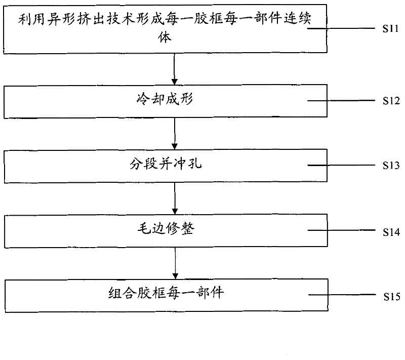
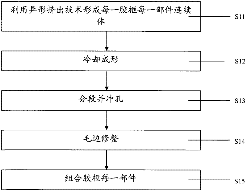
[0016] figure 1 A flow chart of a method for manufacturing a plastic frame according to the present invention is shown. refer to figure 1 , forming a continuum of each part of each plastic frame by using profiled extrusion technology (step S11). The solid plastic enters the barrel through the hopper, and with the cooperation of the barrel and screw made of corrosion-resistant, high-pressure-resistant, and heat-resistant alloy steel, the plastic is crushed, softened, melted, and plasticized (that is, it becomes a viscous fluid. ), exhaust and compaction. Generally, the length of the barrel is 15 to 30 times its diameter, so that the plastic can be fully heated and fully plasticized. The plasticized and compacted plastic in the machine barrel flows into the machine head through the porous filter plate along a certain flow channel through the ne...
PUM
 Abstract
Description
Claims
Application Information