Brake disc continuous siliconizing furnace and working method thereof

A brake disc and silicon infiltration technology, which is applied to furnaces, furnace materials, furnace components, etc., can solve the problems of cost waste, inability to realize continuous assembly line silicon infiltration, and high cost of batch production, and achieve the effect of reducing production costs

Active Publication Date: 2020-03-24
山东道普安制动材料有限公司
View PDF5 Cites 1 Cited by
  • Summary
  • Abstract
  • Description
  • Claims
  • Application Information

AI Technical Summary

Problems solved by technology

[0002] At present, domestic carbon-carbon/carbon-ceramic automobile brake discs are mostly produced by induction vacuum siliconizing furnaces, with a temperature of 1850°C to 1450°C. Due to the siliconizing process, only furnace batch production can be carried out, and continuous pipeline sil

Method used


Image

  • Brake disc continuous siliconizing furnace and working method thereof

Examples


Example Embodiment

[0029] Example 1:

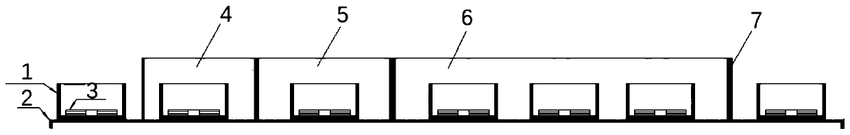
[0030] A brake disc continuous siliconizing furnace includes an outer furnace shell, and the outer furnace shell is provided with a vacuum chamber, a high temperature reaction chamber, and a low temperature buffer chamber, such as figure 1 shown.

[0031] The vacuum chamber, the high temperature reaction chamber and the low temperature buffer chamber are all provided with protective gas inflating devices, and the protective gas provided in the protective gas inflating device is argon. There are vacuum sealing doors on both sides of the vacuum chamber, and the vacuum sealing doors open to the outside of the vacuum chamber. When vacuuming, the two measuring door plates are compacted inward under the action of atmospheric pressure to ensure a certain degree of sealing, and the deoxidization requirement of the absolute vacuum of 50KPa in the furnace can be achieved. There is a 0.5mm gap between the vacuum sealed door and the high temperature reaction chamber....

Example Embodiment

[0034] Example 2:

[0035] A brake disc continuous siliconizing furnace, the structure of which is as described in Embodiment 1, the difference is that the edge of the vacuum sealing door is provided with a sealing strip to further ensure the sealing.

Example Embodiment

[0036] Example 3:

[0037] A brake disc continuous siliconizing furnace, the structure of which is as described in Embodiment 1, the difference is that the heating tube is a squirrel-cage heating tube.


PUM


Abstract

The invention relates to a brake disc continuous siliconizing furnace and a working method thereof, which belong to the technical field of carbon-ceramic brake disc production. The brake disc continuous siliconizing furnace comprises an outer furnace shell, a vacuum chamber, a high-temperature reaction chamber and a low-temperature buffer chamber which are each provided with a protective gas inflation device, wherein vacuum sealing doors are arranged on the two sides of the vacuum chamber; heating pipes are arranged all around the high-temperature reaction chamber and connected with an intelligent temperature controller by means of a pressure regulator; the low-temperature buffer chamber is provided with a heat preservation layer, and the high-temperature reaction chamber communicates withthe low-temperature buffer chamber; a track and a crucible sleeve are arranged at the bottom part of the outer furnace shell, and the crucible sleeve sequentially enters the vacuum chamber, the high-temperature reaction chamber and the low-temperature buffer chamber through the track; the carbon-ceramic brake disc is pushed into the vacuum chamber after being arranged in the crucible sleeve; oxygen in a product is pumped away, an argon gas is introduced to micro-positive pressure, then the product is fed into the high-temperature reaction chamber for dissolved silicon permeation, the productis fed into the low-temperature buffer chamber from the high-temperature reaction chamber for pre-cooling after permeation, and then the product is pushed out of the low-temperature chamber for discharging, thereby achieving the purpose of assembly line siliconizing production, and reducing the production cost of the carbon-ceramic brake disc.

Description

technical field [0001] The invention relates to a brake disc continuous siliconizing furnace and a working method thereof, belonging to the technical field of carbon ceramic brake disc production. Background technique [0002] At present, domestic carbon-carbon / carbon-ceramic automobile brake discs are mostly produced by induction vacuum siliconizing furnaces, with a temperature of 1850°C to 1450°C. Due to the siliconizing process, only furnace batch production can be carried out, and continuous pipeline siliconizing cannot be realized. , resulting in cost waste, and the mass production cost is high and the cycle is long, resulting in multiple heating and cooling of the deposition furnace, high production cost, and a long production cycle limit the development speed of carbon ceramic brake discs. Contents of the invention [0003] Aiming at the deficiencies of the prior art, the present invention provides a continuous siliconizing furnace for brake discs, which has the pur...

Claims


Application Information

Patent Timeline
IPC IPC(8): F27B9/02F27B9/04F27B9/06F27B9/12F27B9/26F27B9/30F27D1/18F27B9/36F16D69/02
CPCF16D69/02F16D2250/0038F27B9/028F27B9/042F27B9/047F27B9/063F27B9/12F27B9/26F27B9/30F27B9/36F27B2009/124F27D1/1858F27M2001/1504
Inventor 史云强杨川殷如帅刘汝强李宗乐
Owner 山东道普安制动材料有限公司
Why Eureka
Try Eureka