
Low-temperature protector of communication electronic system

An electronic system, low temperature protection technology, applied in the direction of automatic disconnection of emergency protection device, emergency protection circuit device, circuit device, etc. , to achieve the effects of low power consumption, restraining temperature drift, and avoiding logic confusion

Inactive Publication Date: 2014-11-05
ZTE CORP +1
View PDF4 Cites 0 Cited by
  • Summary
  • Abstract
  • Description
  • Claims
  • Application Information

AI Technical Summary

Problems solved by technology

After the ambient temperature drops to a certain level, some chip devices can still work normally, while another part of the chip has already worked abnormally due to the low device junction temperature. If the pins of this part of the abnormally working chip are realized through the internal protection circuit To prevent current backfeeding, when it works abnormally, the protection circuit of the pin will not be able to prevent current backfeeding, and some other devices that work normally will continue to inject current into these pins that have lost their protection. , for a long time, these devices with higher minimum junction temperature will lose their efficacy
If the failure of the device is irrecoverable, the board or system will still not work normally after the ambient temperature returns to normal.

Method used


Image

  • Low-temperature protector of communication electronic system
  • Low-temperature protector of communication electronic system
  • Low-temperature protector of communication electronic system

Examples


Embodiment Construction

[0043] The technical solutions of the present invention will be described in detail below in conjunction with the accompanying drawings and preferred embodiments. The following examples are only used to illustrate and explain the present invention, but not to limit the technical solution of the present invention.

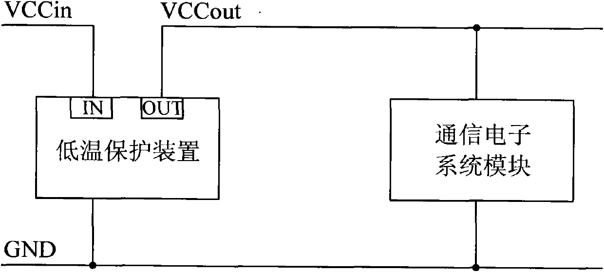
[0044] Such as figure 1 As shown, the present invention designs a low-temperature protection device for communication electronic system modules (single boards or machine frames) that fail to work at low temperatures. The low temperature protection device is configured and installed in the power supply circuit provided for the communication electronic system module, its input terminal (IN) is connected to the input terminal VCCin of the power supply circuit, and its output terminal (OUT) is connected to the output terminal VCCout of the power supply circuit, Its ground terminal is connected to the ground terminal (GND) of the power supply circuit.

[0045] Such as ...


PUM


Abstract

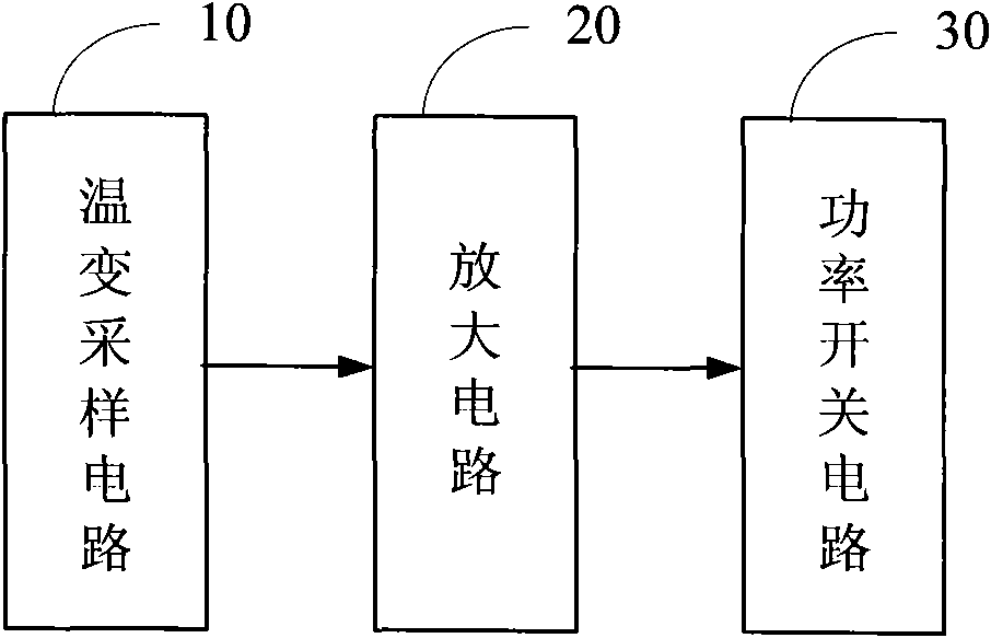
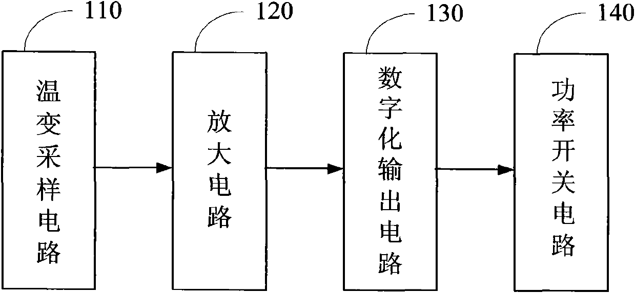
The invention discloses a low-temperature protector of a communication electronic system. The protector is connected with a power supply circuit which is provided for the communication electronic system; and an input end, an output end and an earth terminal of the protector are respectively connected with an input end, an output end and an earth terminal of the power supply circuit correspondingly. The protector comprises a temperature sampling circuit, an amplifying circuit and a power switching circuit, wherein the temperature sampling circuit, the amplifying circuit and the power switching circuit are connected in sequence; the temperature sampling circuit is used for sampling the temperature of the work environment of the communication electronic system and converting the sampled temperature signals into voltage signals as well as outputting the voltage signals to the amplifying circuit; the amplifying circuit is used for amplifying the input voltage signals and outputting the processed analog signals to the power switching circuit; and the power switching circuit is used for controlling the output end of the power supply circuit to switch on or switch off a power supply in accordance with the input analog signals. According to the invention, the communication electronic system can switch off the power supply automatically after the ambient temperature is reduced below a threshold value and also return to normal automatically after the ambient temperature rises to the threshold value.

Description

technical field [0001] The invention relates to the reliability design of electronic circuits in the communication field, in particular to a low temperature protection device for communication electronic systems. Background technique [0002] Communication systems, especially systems such as base stations and remote radio units (RRU, Remote Radio Unit) that require long-term continuous work, may have a huge change in ambient temperature during their long-term continuous work. Too high or too low ambient temperature will cause this type of communication system to work abnormally. Moreover, many systems work abnormally due to this, and still cannot start to work normally after the ambient temperature returns to normal. This is mainly caused by the system not shutting down in time or entering the protection state when the system is working at a too low ambient temperature. [0003] For the abnormal operation of the system caused by too low ambient temperature, many people thi...

Claims


Application Information

Patent Timeline
Patent Type & Authority Patents(China)
IPC IPC(8): H02H5/04H02H3/06
Inventor 赵志刚赵俊锐姜军
Owner ZTE CORP
Learn More