
Automatic maintenance device for standby battery of uninterruptible power system (UPS)

A backup battery, automatic maintenance technology, applied in circuit devices, electrical components, emergency power supply arrangements, etc., can solve the problems of backup battery charge-discharge mode conversion, loss of function, no AC voltage, etc., to avoid battery function loss and extended use. The effect of life and cost saving

Inactive Publication Date: 2011-11-16
BEIJING JINGMEI GRP GENERAL HOSPITAL
View PDF2 Cites 11 Cited by
  • Summary
  • Abstract
  • Description
  • Claims
  • Application Information

AI Technical Summary

Problems solved by technology

[0003] However, the currently used UPS does not have the function of automatic maintenance of backup batteries, and there is no related automatic maintenance device
In units with infrequent power outages, the backup battery that has been in the AC power supply state for a long time cannot perform normal charging and discharging mode conversion, resulting in a decline in the performance of the backup battery, or even loss of function
When there is a real power outage and backup battery power supply is required, the UPS will not be able to function due to the loss of battery function, and there will be no AC voltage output, resulting in the shutdown of the electric load, which will bring huge or even immeasurable and irreparable losses.
[0004] According to the UPS manual, for long-term storage and infrequently used batteries, the charging and discharging operation should be performed every three months, which also increases the labor intensity of the operator.

Method used


Image

  • Automatic maintenance device for standby battery of uninterruptible power system (UPS)
  • Automatic maintenance device for standby battery of uninterruptible power system (UPS)
  • Automatic maintenance device for standby battery of uninterruptible power system (UPS)

Examples


Embodiment 1

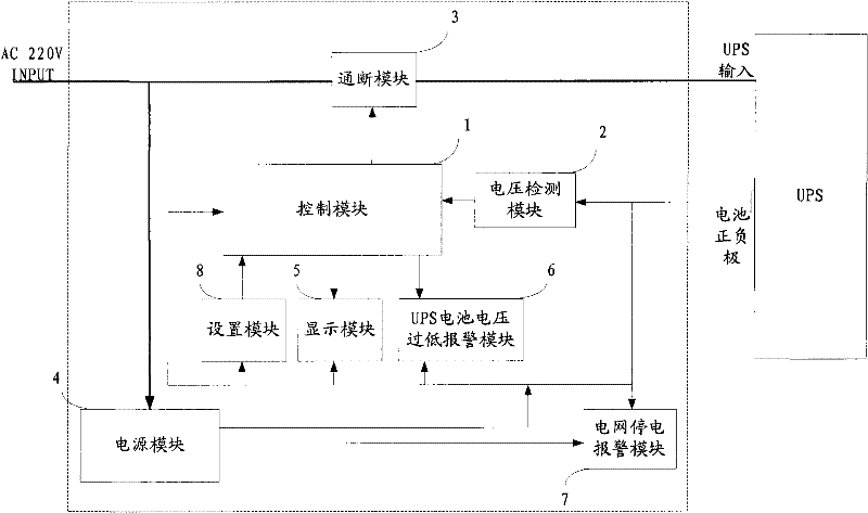
[0037] Such as figure 2 Shown is a circuit diagram of an embodiment of the UPS backup battery automatic maintenance device of the present invention.

[0038] In this embodiment, the control module 1 adopts an AT89S51 single-chip microcomputer, and uses assembly language to write a program.

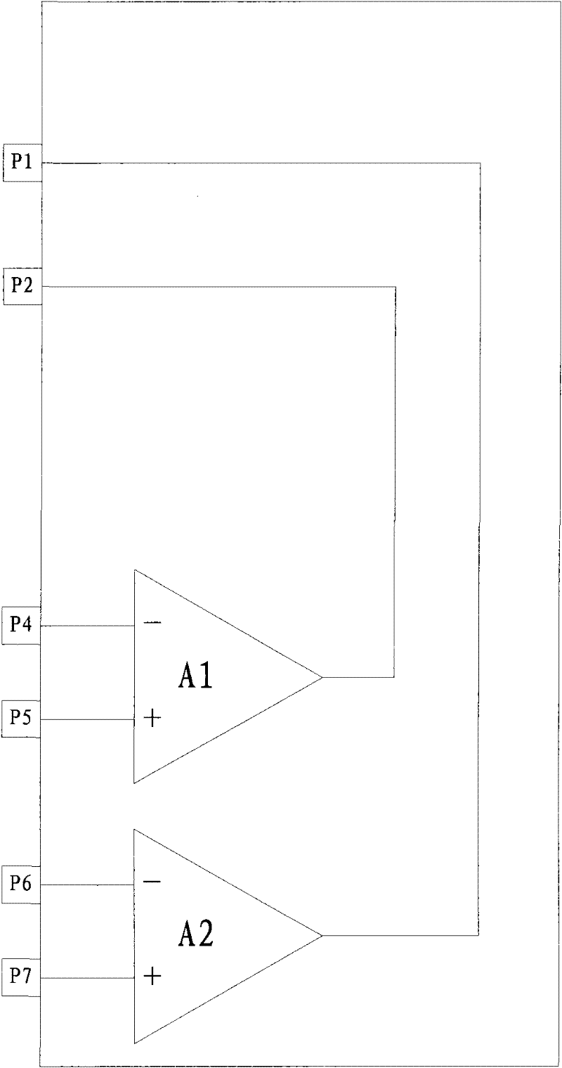
[0039] Voltage detection module 2 adopts LM339 four-voltage comparator, such as image 3 As shown, use two of them - the first voltage comparator A1 and the second voltage comparator A2, the non-inverting input terminal of the first voltage comparator A1 is P5, and the inverting input terminal of the first voltage comparator A1 is P4 , the output terminal of the first voltage comparator A1 is P2, the non-inverting input terminal of the second voltage comparator A2 is P7, the inverting input terminal of the second voltage comparator A2 is P6, and the output terminal of the second voltage comparator A2 is P1; the first optocoupler VL1 and the second optocoupler VL2 adopt 4N-25 optocoupler...


PUM


Abstract

The invention relates to a device for automatically charging and discharging a standby battery of an uninterruptible power system (UPS). The device comprises a control module, a voltage detection module, a switching on / off module and the like, wherein the switching on / off module is arranged at the input end of an AC power supply which supplies power to the UPS; the voltage detection module detects the voltage of the standby battery of the UPS; the switching on / off module and the voltage detection module are both electrically connected with the control module; the control module performs timing according to set automatic maintenance time, controls the switching on / off module to cut AC off to discharge the standby battery of the UPS when time obtained by the timing is equal to the maintenance time, and controls the switching on / off module to switch the AC on and performs maintenance time timing again when the voltage detection module detects the voltage of the standby battery of the UPS is reduced to a certain set value. Manual intervention is not required by the whole maintenance process to save labor cost at the same time of prolonging the service life of the UPS. Simultaneously, the invention also provides a UPS battery under voltage alarming module and a power grid power failure alarming module, which aim to timely give an alarm in exceptions.

Description

technical field [0001] The invention is applied to the field of electronic work, and relates to a device for automatically charging and discharging UPS backup batteries. Background technique [0002] UPS (Uninterruptible Power System, uninterruptible power supply), as an accessory product for electronic computers and other electronic equipment that requires uninterruptible power supply, is widely used by users because it can continue to supply power to the connected loads when the power grid fails. [0003] However, the currently used UPS does not have a backup battery automatic maintenance function, and there is no related automatic maintenance device. In units with infrequent power outages, the backup battery that has been in the AC power supply state for a long time cannot perform normal charging and discharging mode conversion, causing the performance of the backup battery to decline, or even lose its function. When there is a real power outage and the backup battery is...

Claims


Application Information

Patent Timeline
IPC IPC(8): H02J9/06
Inventor 刘长水
Owner BEIJING JINGMEI GRP GENERAL HOSPITAL
Learn More