
Automatic Q value adjustment amplitude limiting circuit

An automatic adjustment and limiting circuit technology, applied in the direction of limiting the amplitude with diodes, can solve the problems of frequent on and off, reduced system action distance, large periodic noise, etc., to reduce the layout area, reduce the pulse noise, The effect of eliminating influence

Inactive Publication Date: 2011-11-16
GUANGZHOU SYSUR MICROELECTRONICS
View PDF3 Cites 20 Cited by
  • Summary
  • Abstract
  • Description
  • Claims
  • Application Information

AI Technical Summary

Problems solved by technology

It is difficult to adjust the operating distance between the reader and the tag, which is not in line with the actual application; changing the input capacitance of the tag and reducing the induced voltage by changing the resonant frequency will reduce the operating distance of the system, and the capacitor in the design will occupy a larger layout area. Does not meet low-cost design requirements
The traditional limiter circuit has a great influence on the resonance of the antenna, and because of its frequent on and off, it generates a large periodic noise and during the operation of the modulation circuit, the limiter circuit will affect the sideband modulation signal

Method used


Image

  • Automatic Q value adjustment amplitude limiting circuit
  • Automatic Q value adjustment amplitude limiting circuit
  • Automatic Q value adjustment amplitude limiting circuit

Examples


Embodiment Construction

[0014] The present invention will be further elaborated below in conjunction with the accompanying drawings.

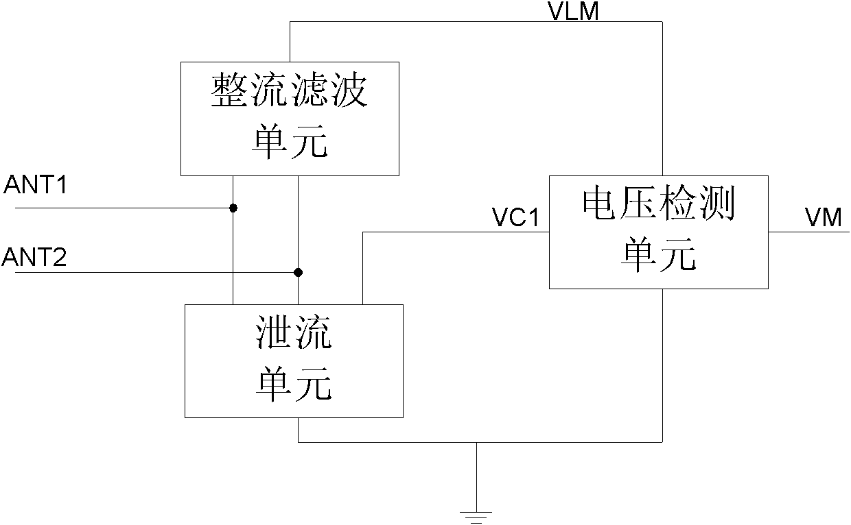
[0015] The present invention adopts the self-adaptive adjustment method of the antenna Q value, by adaptively adjusting the load on the antenna end and then adjusting the antenna Q value to realize amplitude limiting. When the tag antenna circuit composed of inductance and capacitance occurs parallel resonance, its peak voltage is determined by The Q value of the antenna is determined by the inductive parasitic resistance and the load of the antenna inductance that affect the Q value. The antenna Q value adaptive adjustment limiter circuit structure is realized by the voltage negative feedback system.

[0016] Such as figure 1 As shown, the Q value automatic adjustment limiter circuit of the present invention includes a rectification filter unit, a voltage detection unit and a discharge unit, wherein, ANT1 and ANT2 at both ends of the antenna are connected with the re...


PUM


Abstract

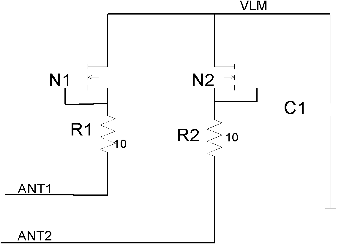
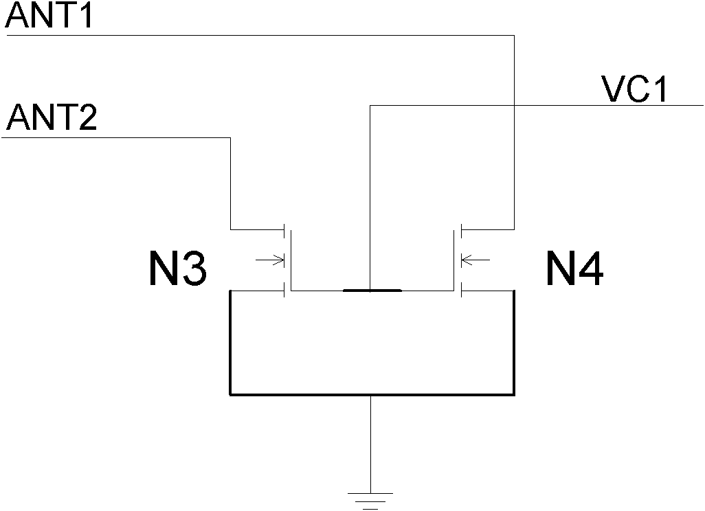
The invention discloses a low-cost, low-power consumption and high-performance automatic Q value adjustment amplitude limiting circuit, which comprises a rectification filter unit, a voltage detection unit and a drain unit, wherein the rectification filter circuit samples antenna voltage, and performs shaping processing to form sampled voltage VLM; the voltage detection unit compares the sampled voltage VLM with set internal reference voltage to obtain a drain control signal VC1; and the drain unit controls the current of a low-impedance path from an antenna to the ground according to the drain control signal VC1. The rectification filter unit of the circuit samples the voltage at the two ends of the antenna by utilizing a sampling diode and a sampling capacitor, the introduction of the sampling diode is favorable for reducing the influence of the amplitude limiting circuit on antenna resonance, and the adoption of the sampling capacitor greatly reduces pulse noises produced when the amplitude limiting circuit works; and a voltage division diode of the voltage detection unit adopts a diode connection method for P-channel metal oxide semiconductor (PMOS) transistors, and by the method, a territory area can be reduced and the influence of bulk effects on the circuit can be eliminated.

Description

technical field [0001] The invention relates to a Q value automatic adjustment limiter circuit, in particular to a low-cost, low power consumption and high-performance Q value automatic adjustment limiter circuit amplitude limitation suitable for RFID tag chips. Background technique [0002] With its outstanding advantages, radio frequency identification technology is running through the links of production, life, trade and circulation, especially the development of the service industry now, which provides a broad development platform for radio frequency identification. The RFID system consists of tags and readers. The development of low-cost, low-power and high-performance tag chips is becoming one of the bottlenecks in promoting the popularization of RFID technology. [0003] The analog front end is the air interface between the radio frequency identification tag chip and the outside world, and it mainly completes the functions of energy acquisition and data transmission a...

Claims


Application Information

Patent Timeline
Patent Type & Authority Applications(China)
IPC IPC(8): H03G11/02
Inventor 胡建国张俊丁颜玉王德明谭洪舟徐永钊
Owner GUANGZHOU SYSUR MICROELECTRONICS
Learn More