
System and method for detecting sub-optical fibers, ODN (optical distribution network) and optical splitter

A branch optical fiber and detection system technology, which is applied in the field of optical network communication, can solve the problems of low light utilization rate, high storage and system maintenance costs, and low signal-to-noise ratio of reflected light, so as to improve light utilization rate and reduce storage and maintenance Cost, the effect of improving test accuracy

Active Publication Date: 2011-11-16
HUAWEI TECH CO LTD
View PDF4 Cites 32 Cited by
  • Summary
  • Abstract
  • Description
  • Claims
  • Application Information

AI Technical Summary

Problems solved by technology

Therefore, the branch fiber detection scheme in the prior art has the problem of low light utilization rate, which easily causes the signal-to-noise ratio of the reflected light detected by the OTDR on the trunk fiber to be too low, which may cause false detection
On the other hand, in the branch fiber detection solution in the prior art, it is necessary to configure different bandpass filters for each branch fiber at the user-side port of the optical splitter, which will lead to high storage and system maintenance costs

Method used


Image

  • System and method for detecting sub-optical fibers, ODN (optical distribution network) and optical splitter
  • System and method for detecting sub-optical fibers, ODN (optical distribution network) and optical splitter
  • System and method for detecting sub-optical fibers, ODN (optical distribution network) and optical splitter

Examples


Embodiment Construction

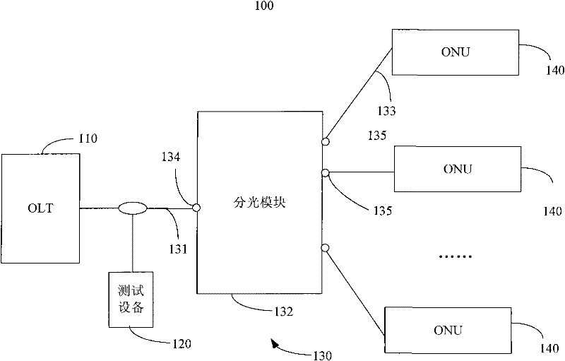
[0021] The branch fiber detection method, system and optical splitter provided by the embodiments of the present invention will be described in detail below with reference to the accompanying drawings.

[0022] The various technical solutions provided by the embodiments of the present invention are applicable to point-to-multipoint optical fiber networks, such as a passive optical network (PON) system. For ease of understanding, the following embodiments are described by taking the application in the PON system as an example. However, it should be understood that the various technical solutions provided by the embodiments of the present invention are not limited to the application in the PON system. Those skilled in the art can use the following specific It is known from the content of the implementation manner that various technical solutions provided in the embodiments of the present invention may also be applied to other optical fiber networks.

[0023] In order to solve th...


PUM


Abstract

The embodiment of the invention provides a system for detecting sub-optical fibers, comprising a main optical fiber, a light splitting module and multiple sub-optical fibers, wherein the light splitting module comprises at least one light splitter; each port of the light splitting module is provided with an optical film which is used for carrying out bandpass filtering on optical signals sent to the ports of the light splitter in accordance with a preset rule, and the optical films can cause pass bands of test links corresponding to sub-optical signals to be different; test equipment is used for selecting test wavelength sub-bands which are matched with the optical films of the ports of the light splitter in testing light spectrums in accordance with ports of the light splitter corresponding to to-be-tested sub-optical fibers, sending test signals corresponding to the selected test wavelength sub-bands to the ODN, receiving reflected signals which are formed by reflecting the test signals on the corresponding sub-optical fibers and acquiring the channel characteristics of the to-be-tested sub-optical fibers in accordance with the reflected signals. The embodiment of the invention also provides a method for detecting the sub-optical fibers, an ODN (optical distribution network) and an optical splitter.

Description

technical field [0001] The present invention relates to the technical field of optical network communication, in particular to a branch optical fiber detection system and method, and an optical distribution network and an optical splitter that can be used in the above branch optical fiber detection system. Background technique [0002] A passive optical network (Passive Optical Network, PON) system is a point-to-multipoint optical access network system, which usually includes an optical line terminal (Optical Line Terminal, OLT) at the central office and multiple optical Network unit (Optical Network Unit, ONU). The OLT and the ONU are connected by using an optical distribution network (Optical Distribution Network, ODN), and the ODN usually includes an optical splitter. The optical splitter can be used to realize the distribution of downlink optical signals from the central office to corresponding users through the branch optical fiber, and converge the upstream optical si...

Claims


Application Information

Patent Timeline
IPC IPC(8): H04B10/08H04B10/20H04B10/077
CPCH04Q2011/0083H04B10/0773H04Q11/0067
Inventor 温运生赵峻王波单小磊王世军
Owner HUAWEI TECH CO LTD
Learn More